2-62
[7]
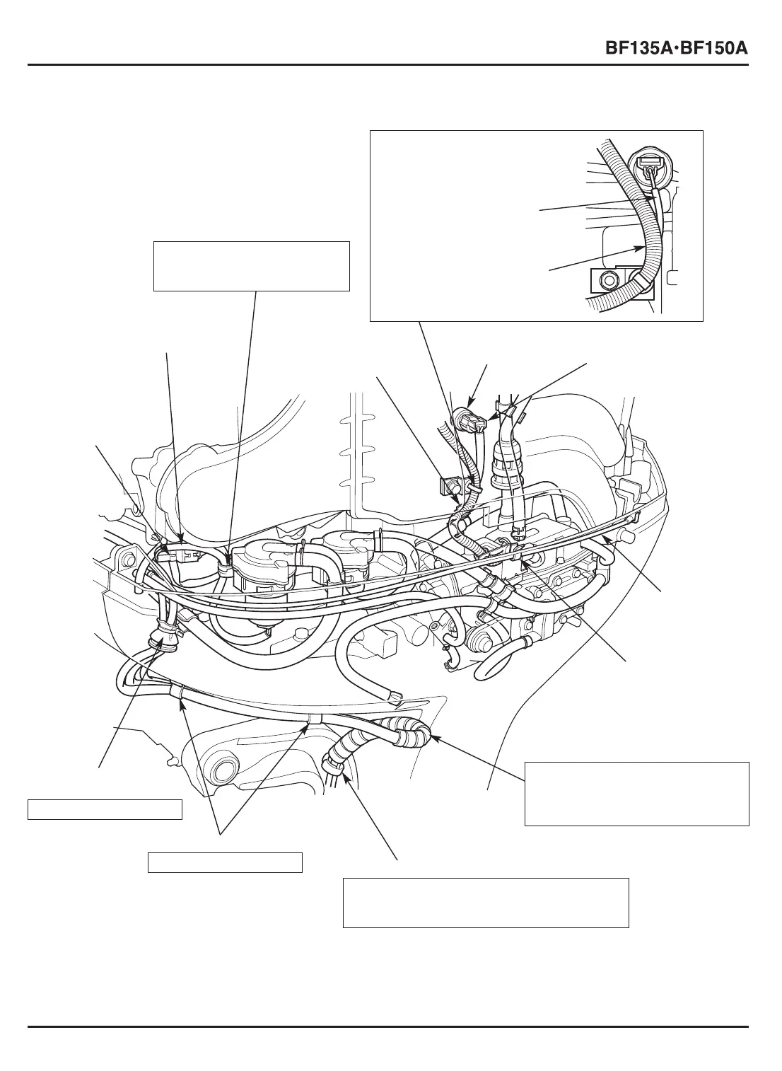
KNOCK SENSOR
1P CONNECTOR
[6]
KNOCK SENSOR
[4] MAIN WIRE
HARNESS
[5] HARNESS BAND CLIP
Clamp the main wire
harness and the knock
sensor wire.
[5]-1 KNOCK SENSOR
WIRE
[5]-2 MAIN WIRE
HARNESS
[1]
WATER LEVEL
SENSOR
2P CONNECTOR
[2] WATER LEVEL
SENSOR WIRE
[10] SPIRAL TUBE
Wind the spiral tube around the
power tilt motor wire, trim angle
sensor wire and the speed sensor
tube A.
[11] WIRE HARNESS CLIP
Clamp the power tilt motor wire, trim angle
sensor wire and the speed sensor tube A.
Avoid clamping on the spiral tube.
[13]
UNDERCASE
GROMMET C
INSTALLATION: P. 2-56
[12] 14 mm CLIPS
INSTALLATION: P. 2-63
[9]
CABLE CLIP
[8]
COVER LOCK
CABLE A
[3] HARNESS CLIP
Clamp the main wire harness
and the water level sensor
wire at the taped part.
 Loading...