4-29
dummyheaddummyhead
PGM-FI SYSTEM
3. IAT Sensor Voltage Output Line Short Circuit
Inspection
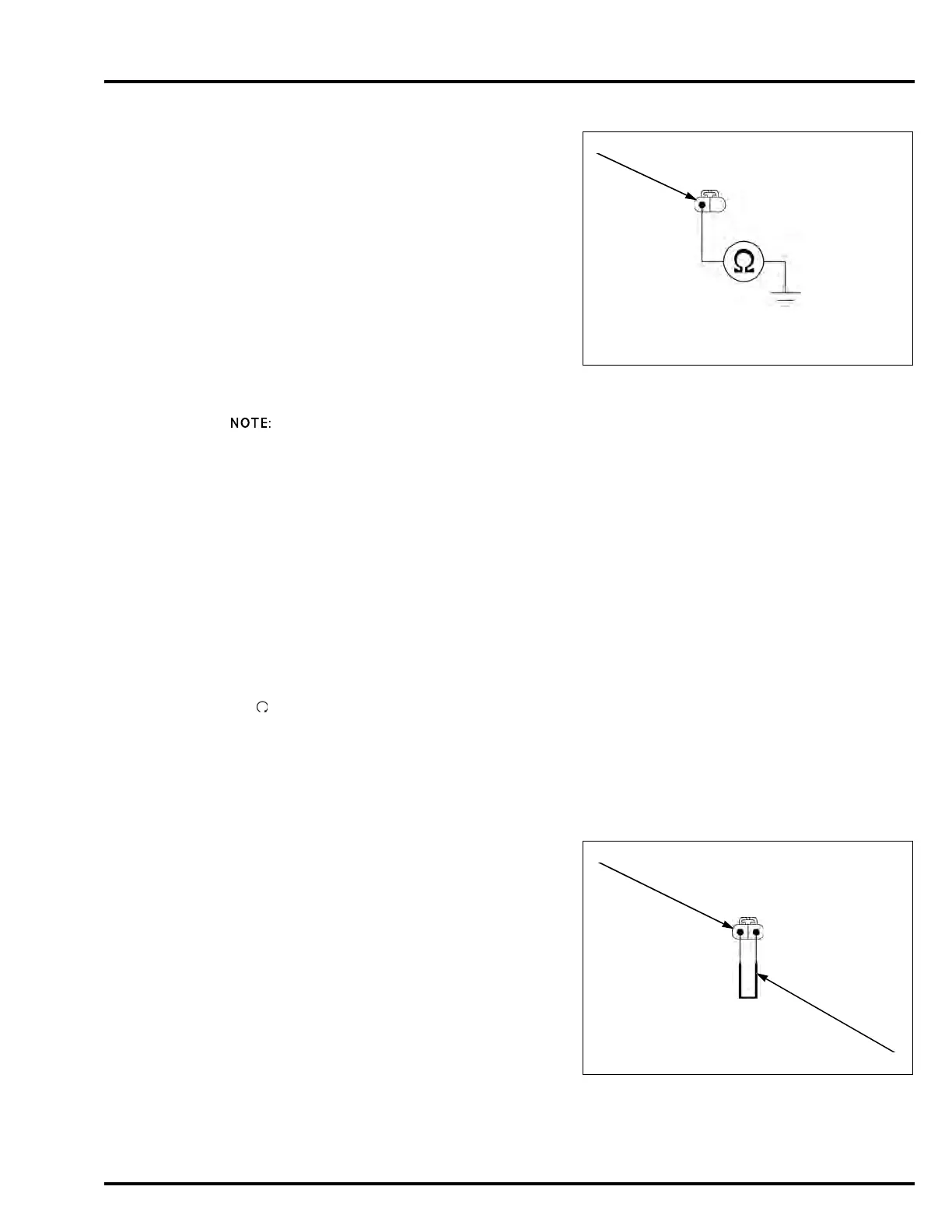
Turn the ignition switch OFF.
Check for continuity between the IAT sensor 2P
(Black) connector [1] of the wire harness side and
ground.
Is there continuity?
YES – Short circuit in the Gray/blue wire
NO – Replace the ECM/PCM with a known good
one, and recheck.
DTC 9-2 (IAT SENSOR HIGH
VOLTAGE)
• NC700X/XA/S/SA:
Before starting the inspection, check for loose or
poor contact on the IAT sensor 2P (Black) connector
and ECM 33P (Black) connector, then recheck the
DTC.
• NC700XD/SD:
Before starting the inspection, check for loose or
poor contact on the IAT sensor 2P (Black) connector
and PCM 33P (Gray) connector, then recheck the
DTC.
• If the ECM/PCM is replaced, perform the following:
– Key Registration Procedure (page 23-6)
– Clutch Initialize Learning Procedure (NC700XD/
SD) (page 12-120)
1. IAT Sensor System Inspection
Turn the ignition switch ON and engine stop switch
"".
Check the IAT sensor with the HDS pocket tester.
Is about 5 V indicated?
YES – GO TO STEP 2.
NO – Intermittent failure
2. IAT Sensor Inspection
Turn the ignition switch OFF.
Disconnect the IAT sensor 2P (Black) connector [1].
Connect the IAT sensor 2P (Black) connector
terminals at the wire harness side with a jumper wire
[2].
Turn the ignition switch ON.
Check the IAT sensor with the HDS pocket tester.
Is about 0 V indicated?
YES – Faulty IAT sensor
NO – GO TO STEP 3.
Connection: Gray/blue – Ground
Connection: Gray/blue – Green/yellow