4-31
dummyheaddummyhead
PGM-FI SYSTEM
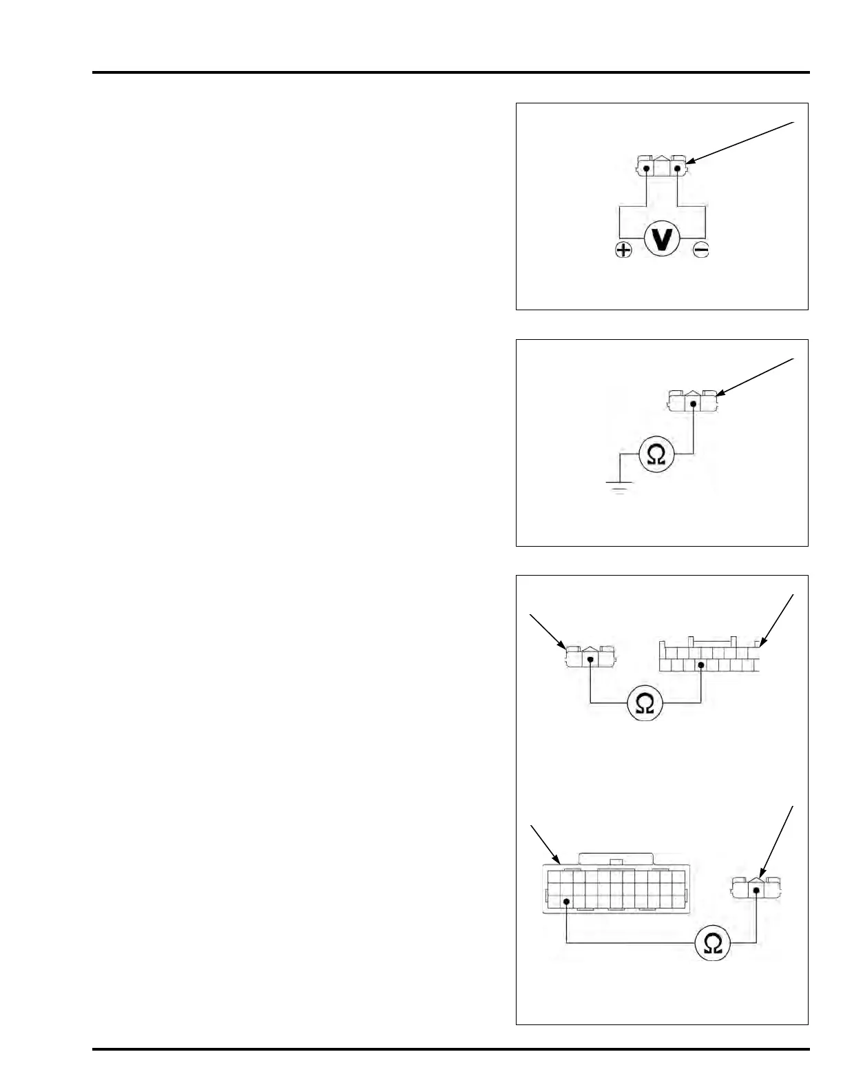
3. VS Sensor Input Voltage Inspection
Turn the ignition switch OFF.
Disconnect the VS sensor 3P (Black) connector [1].
Turn the ignition switch ON.
Measure the voltage at the VS sensor 3P (Black)
connector of the wire harness side.
Is there battery voltage?
YES – GO TO STEP 4.
NO – • Open circuit in the Pink/blue wire
• Open circuit in the Green/red wire
4. VS Sensor Signal Line Short Circuit Inspection
Turn the ignition switch OFF.
Check for continuity between the VS sensor 3P
(Black) connector [1] of the wire harness side and
ground.
Is there continuity?
YES – Short circuit in the Pink/green wire
NO – GO TO STEP 5.
5. VS Sensor Signal Line Open Circuit Inspection
NC700X/XA/S/SA:
Disconnect the combination meter 16P (Gray)
connector [1].
Check for continuity between the VS sensor 3P
(Black) connector [2] and combination meter 16P
(Gray) connector of the wire harness side.
NC700XD/SD:
Disconnect the PCM 33P (Gray) connector [3].
Check for continuity between the VS sensor 3P
(Black) connector [4] and PCM 33P (Gray)
connector of the wire harness side.
Is there continuity?
YES – GO TO STEP 6.
NO – Open circuit in the Pink/green wire
Connection: Pink/blue (+) – Green/red (–)
Standard: Battery voltage
Connection: Pink/green – Ground
Connection: Pink/green – Pink/green
Connection: Pink/green – Pink/green
TOOL:
Test probe 07ZAJ-RDJA110
NC700X/XA/S/SA:
NC700XD/SD:
P/G
[1]
[2]
P/G
[4]
[3]
P/G
P/G

 Loading...