Abbreviations
126 customer.honeywell.com 70-6925
For example, the hot deck control point is reset upward as
the outdoor air temperature decreases. Also know as
“compensation control.”
Restrictor: A device in an air line that limits the flow of air.
Return air: Air entering an air handling system from the
occupied space.
Reverse acting (RA): A reverse-acting thermostat or controller
decreases the branchline pressure on an increase in the
measured variable and increases the branchline pressure on
a decrease in the variable. A reverse-acting valve actuator
retracts the shaft on an increase in branchline pressure and
extends the shaft on a decrease in pressure.
Sensing element: A device that detects and measures the
controlled variable (e.g., temperature, humidity).
Sensor: A device placed in a medium to be measured or
controlled that has a change in output signal related to a
change in the sensed medium.
Sensor Span: The variation in the sensed media that causes
the sensor output to vary between 3 and 15 psi.
Setpoint: The value on the controller scale at which the
controller is set (e.g., the desired room temperature set on a
thermostat). The desired control point.
Supply air: Air leaving an air handling system.
Thermostat: A device that responds to changes in temperature
and outputs a control signal (branchline pressure). Usually
mounted on a wall in the controlled space.
Throttling range: Related to proportional band, and expressed
in values of the controlled variable (e.g., degrees, percent
relative humidity, pounds per square inch) rather than in
percent.
ABBREVIATIONS
The following port abbreviations are used in drawings of relays
and controllers:
B — Branch
C — Common
E — Exhaust
M —Main
O — Normally connected*
X — Normally disconnected*
P — Pilot (P1 and P2 for dual-pilot relays)
S — Sensor (S1 and S2 for dual-input controllers)
N.C. — Normally closed
N.O. — Normally open
* The normally connected and common ports are connected
on a fall in pilot pressure below the relay setpoint, and the
normally disconnected port is blocked. On a rise in pilot
pressure above the relay setpoint, the normally
disconnected and common ports are connected and the
normally connected port is blocked. Refer to Figure 37 in
RELAYS AND SWITCHES.
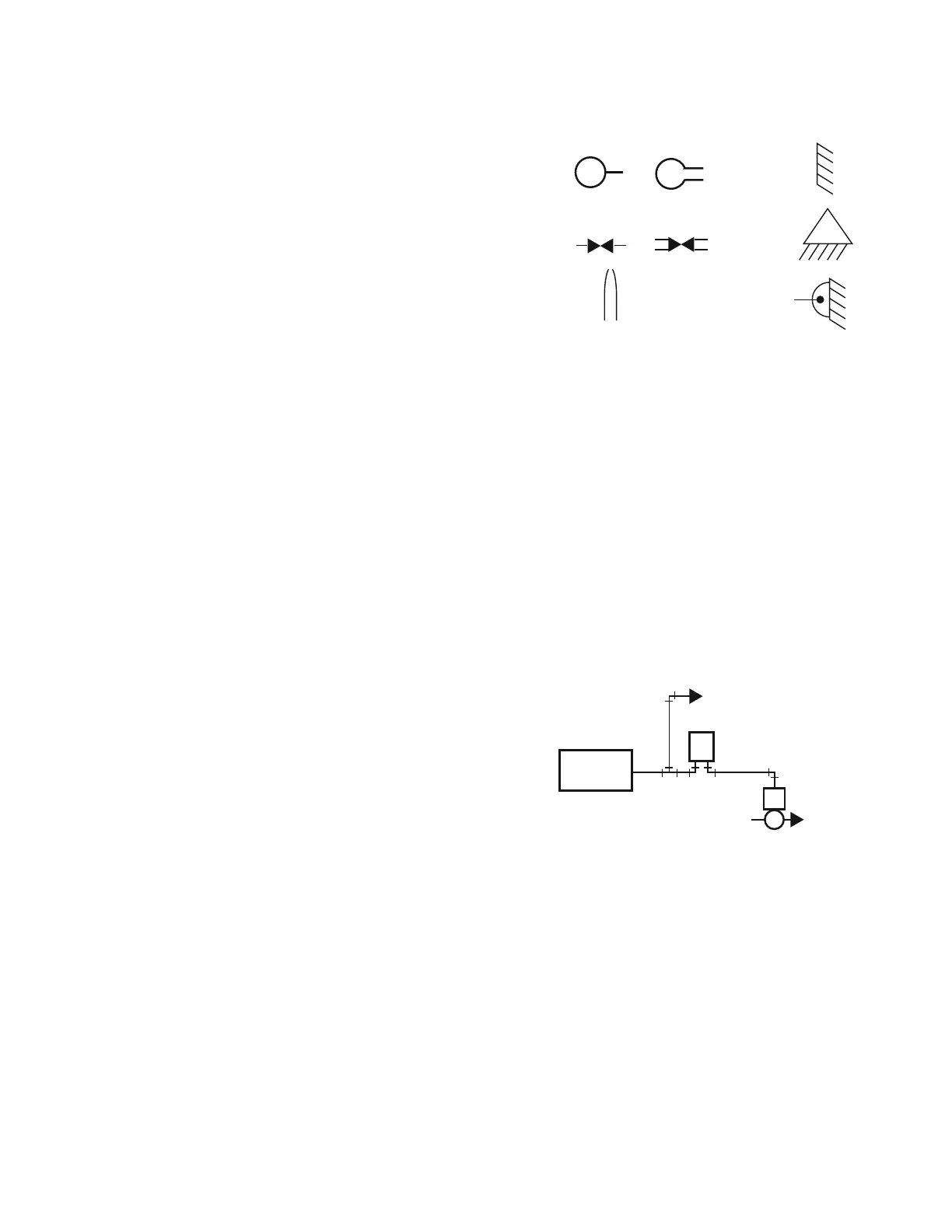
SYMBOLS
BASIC PNEUMATIC CONTROL SYSTEM
General
A pneumatic control system is made up of the following
elements:
— Compressed air supply system
— Main line distribution system
— Branchlines
— Sensors
— Controllers
—Actuators
— Final control elements (e.g., valves, dampers)
A basic pneumatic control system consists of an air supply, a
controller such as a thermostat, and an actuator positioning a
valve or damper (Fig. 1).
Fig. 1. Basic Pneumatic Control System.
The controller receives air from the main line and regulates its
output pressure (branchline pressure) as a function of the
temperature, pressure, humidity, or other variable. The
branchline pressure from the controller can vary from zero to
full mainline pressure. The regulated branchline pressure
energizes the actuator, which then assumes a position
proportional to the branchline pressure applied. The actuator
usually goes through its full stroke as the branchline pressure
changes from 3 psi to 13 psi. Other pressure ranges are
available.
In a typical control system, the final control element (a valve or
a damper) is selected first because it must produce the desired
control results. For example, a system designed to control the
flow of water through a coil requires a control valve. The type of
valve, however, depends on whether the water is intended for
M
M
OR
OR
MAIN AIR
SUPPLY
RESTRICTOR
NOZZLE
FIXED POINT
FULCRUM
PIVOT POINT
C1082
C2353
COMPRESSED
AIR SUPPLY
SYSTEM
MAIN BRANCH
ACTUATOR
VALVE
THERMOSTAT
TO OTHER
CONTROLLERS
M
B
 Loading...