Air Supply Equipment
130 customer.honeywell.com 70-6925
Relays and Switches
Relays are used in control circuits between controllers and
controlled devices to perform a function beyond the capacity of
the controllers. Relays typically have diaphragm logic
construction (Fig. 10) and are used to amplify, reverse,
average, select, and switch controller outputs before being sent
to valve and damper actuators.
Fig. 10. Typical Switching Relay.
The controlling pressure is connected at the pilot port (P), and
pressures to be switched are connected at the normally
connected port (O) or the normally disconnected port (X). The
operating point of the relay is set by adjusting the spring
pressure at the top of the relay.
When the pressure at the pilot port reaches the relay operating
point, it pushes up on the diaphragm in the control chamber and
connects pressure on the normally disconnected port (X) to the
common port as shown. If the pilot pressure falls below the
relay setpoint, the diaphragm moves down, blocks the normally
disconnected (X) port, and connects the normally connected
port (O) to the common port.
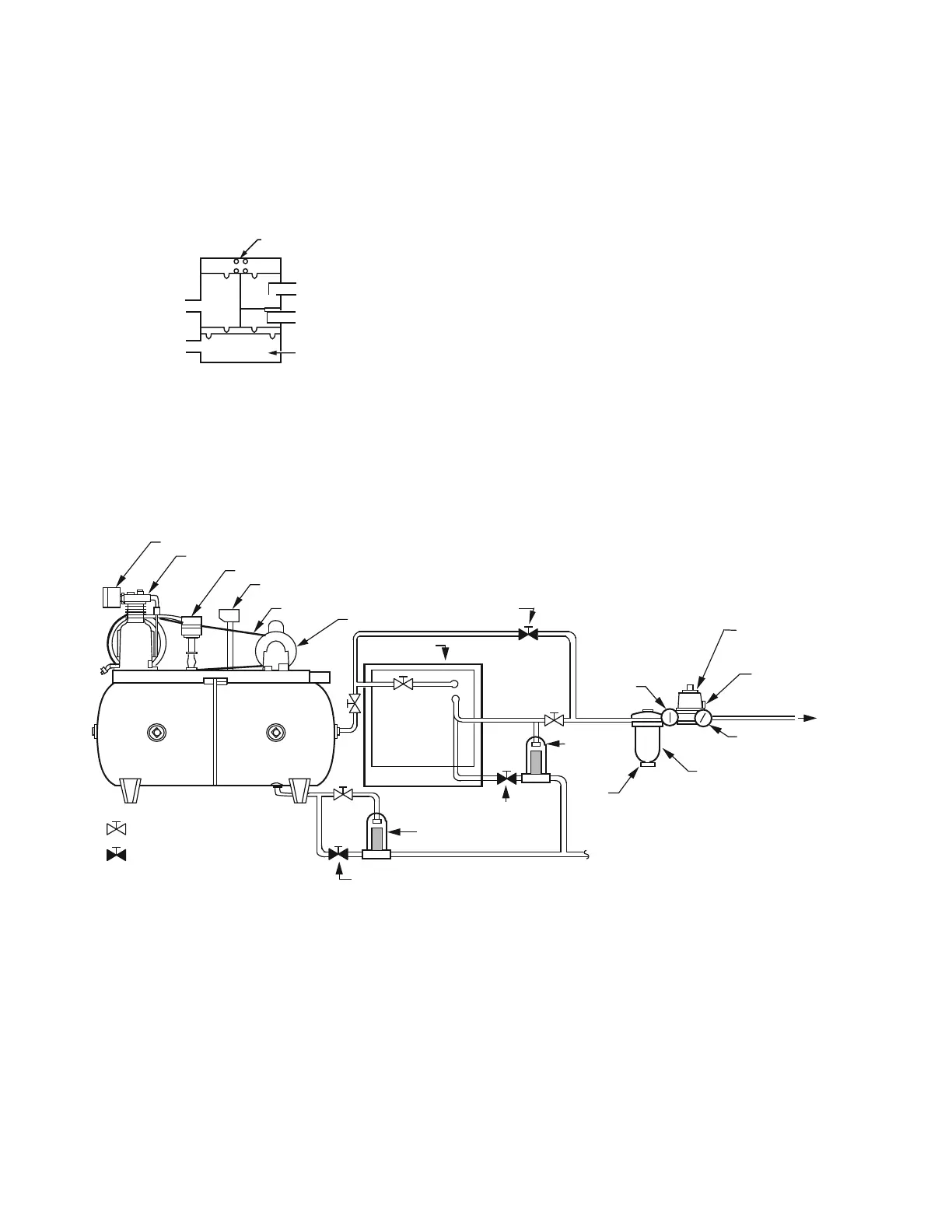
AIR SUPPLY EQUIPMENT
General
A pneumatic control system requires a supply of clean, dry,
compressed air. The air source must be continuous because
many pneumatic sensors, controllers, relays, and other devices
bleed air. A typical air supply system includes a compressor, an
air dryer, an air filter, a pressure reducing valve, and air tubing
to the control system (Fig. 11).
The following paragraphs describe the compressor, filter,
pressure reducing valves, and air drying techniques. For
information on determining the moisture content of compressed
air, refer to the General Engineering Data section.
Fig. 11. Typical Air Supply.
Air Compressor
The air compressor provides the power needed to operate all
control devices in the system. The compressor maintains
pressure in the storage tank well above the maximum required
in the control system. When the tank pressure goes below a
minimum setting (usually 70 to 90 psi), a pressure switch starts
the compressor motor. When the tank pressure reaches a high-
limit setting, the pressure switch stops the motor. A standard
tank is typically large enough so that the motor and compressor
operate no more than 50 percent of the time, with up to twelve
motor starts per hour.
Some applications require two compressors or a dual
compressor. In a dual compressor, two compressors operate
alternately, so wear is spread over both machines, each
capable of supplying the average requirements of the system
without operating more than half the time. In the event of failure
of one compressor, the other assumes the full load.
Contamination in the atmosphere requires a compressor intake
filter to remove particles that would damage the compressor
pump. The filter is essential on oil-less compressors because a
contaminated inlet air can cause excessive wear on piston
rings. The intake filter is usually located in the equipment room
with the compressor, but it may be located outdoors if clean
COMMON
PORT
P
PILOT
PORT
CONTROL
CHAMBER
X
O
NORMALLY
CONNECTED PORT
NORMALLY
DISCONNECTED PORT
C2608
SPRING
AIR DRYER
MOTOR
INTAKE FILTER
COMPRESSOR
PRESSURE SWITCH
HIGH PRESSURE SAFETY RELIEF VALVE
DRIVE BELT
STORAGE
TANK
NORMALLY OPEN
SERVICE/TEST VALVE
NORMALLY CLOSED
SERVICE/TEST VALVE
C2617-2
HIGH-PRESSURE
GAGE
DRAIN
COCK
PRESSURE
REDUCING
VALVE
SAFETY REFIEF VALVE
LOW-PRESSURE GAGE
MAIN AIR
TO SYSTEM
TEST COCK
TEST COCK
AUTO TRAP
AUTO
SEPARATOR
FILTER/TRAP
SERVICE
BYPASS
VALVE
PIPED TO DRAIN
SUBMICRON
FILTER
 Loading...