Actuators and Final Control Elements
70-6925 137
Humidistats
and
Thermostats Controllers Sensors Relays Switches Actuators Valves Accessories
Engineering
Guide
Cross
Reference
The velocity sensor measures actual velocity and does not
require the conversion of velocity pressure to velocity. Although
the sensor is typically used in duct air velocity applications, it
can accurately sense velocities as low as 100 feet per minute.
Flow-limiting orifices inserted into the sensor sampling tube can
measure velocity ranges up to 3,500 feet per minute.
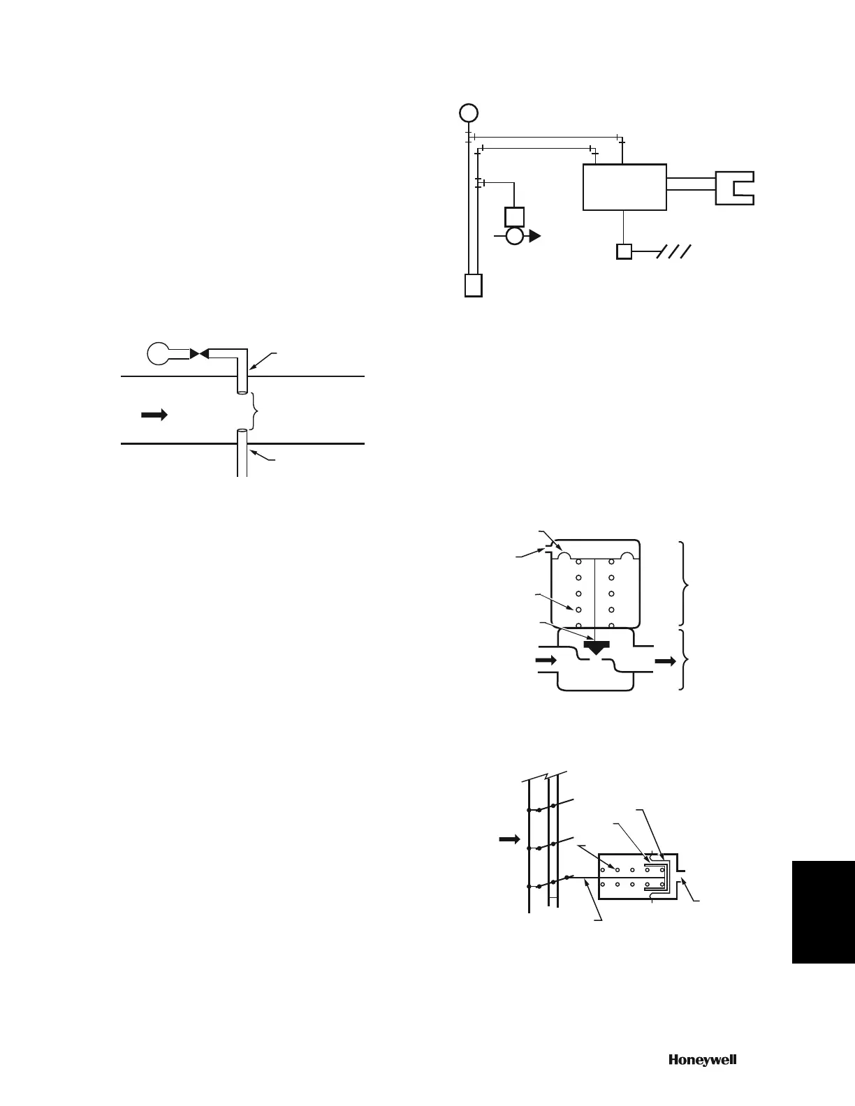
Figure 24 shows the operation of a velocity sensor. A restrictor
supplies compressed air to the emitter tube located in the air
stream to be measured. When no air is flowing in the duct, the
jet of air from the emitter tube impinges directly on the collector
tube and maximum pressure is sensed. Air flowing in the duct
blows the air jet downstream and reduces the pressure on the
collector tube. As the duct air velocity increases, less and less
of the jet enters the collector tube. The collector tube is
connected to a pressure amplifier to produce a usable output
pressure and provide direct or reverse action.
Fig. 24. Velocity Sensor Operation.
A controller connected to the pressure amplifier includes
setpoints for maximum and minimum dual air velocity limits.
This allows the air volume to be controlled between the limits by
a thermostat or another controller.
Two models of the controller are available. One model operates
with a one-pipe, bleed-type thermostat, and the other with a
two-pipe thermostat. The two-pipe model also allows
sequencing for reheat applications.
Figure 25 shows a typical application of a thermostat and
velocity controller on a Variable Air Volume (VAV) terminal unit
with hot water reheat. The thermostat senses a change in room
temperature and resets the velocity setpoint of the velocity
controller. The controller repositions the VAV damper to
increase or decrease airflow accordingly. If a change in duct
static pressure modifies the flow, the controller repositions the
actuator to maintain the correct flow. The reheat valve operates
only when the thermostat has reset the velocity setpoint down
to minimum airflow and the thermostat calls for heating.
Fig. 25. VAV Box Velocity Controller Control System.
ACTUATORS AND FINAL CONTROL
ELEMENTS
A pneumatic actuator and final control element such as a valve
(Fig. 26) or damper (Fig. 27) work together to vary the flow of
the medium passing through the valve or damper. In the
actuator, a diaphragm and return spring move the damper push
rod or valve stem in response to changes in branchline
pressure.
Fig. 26. Pneumatic Actuator and Valve.
Fig. 27. Pneumatic Actuator and Damper.
M
AIR FLOW
EMITTER TUBE
GAP
COLLECTOR
TUBE
TO PRESSURE
AMPLIFIER
C2610
M
VELOCITY
SENSOR IN
DUCTWORK
VAV BOX
DAMPER
DAMPER
ACTUATOR
VELOCITY
CONTROLLER
VAV BOX
REHEAT VALVE
ROOM
THERMOSTAT
M10296
BRANCH
LINE
SPRING
VALVE
STEM
INLET
FLOW
OUTLET
FLOW
DIAPHRAGM
VALVE
ACTUATOR
VALVE
M10361
C2611
DAMPER
IRFLOW
PUSH
ROD
DAMPER
ACTUATOR
SPRING
PISTON
ROLLING
DIAPHRAGM
BRANCH
LINE
 Loading...