Thermostats
70-6925 133
Humidistats
and
Thermostats Controllers Sensors Relays Switches Actuators Valves Accessories
Engineering
Guide
Cross
Reference
Air Filter
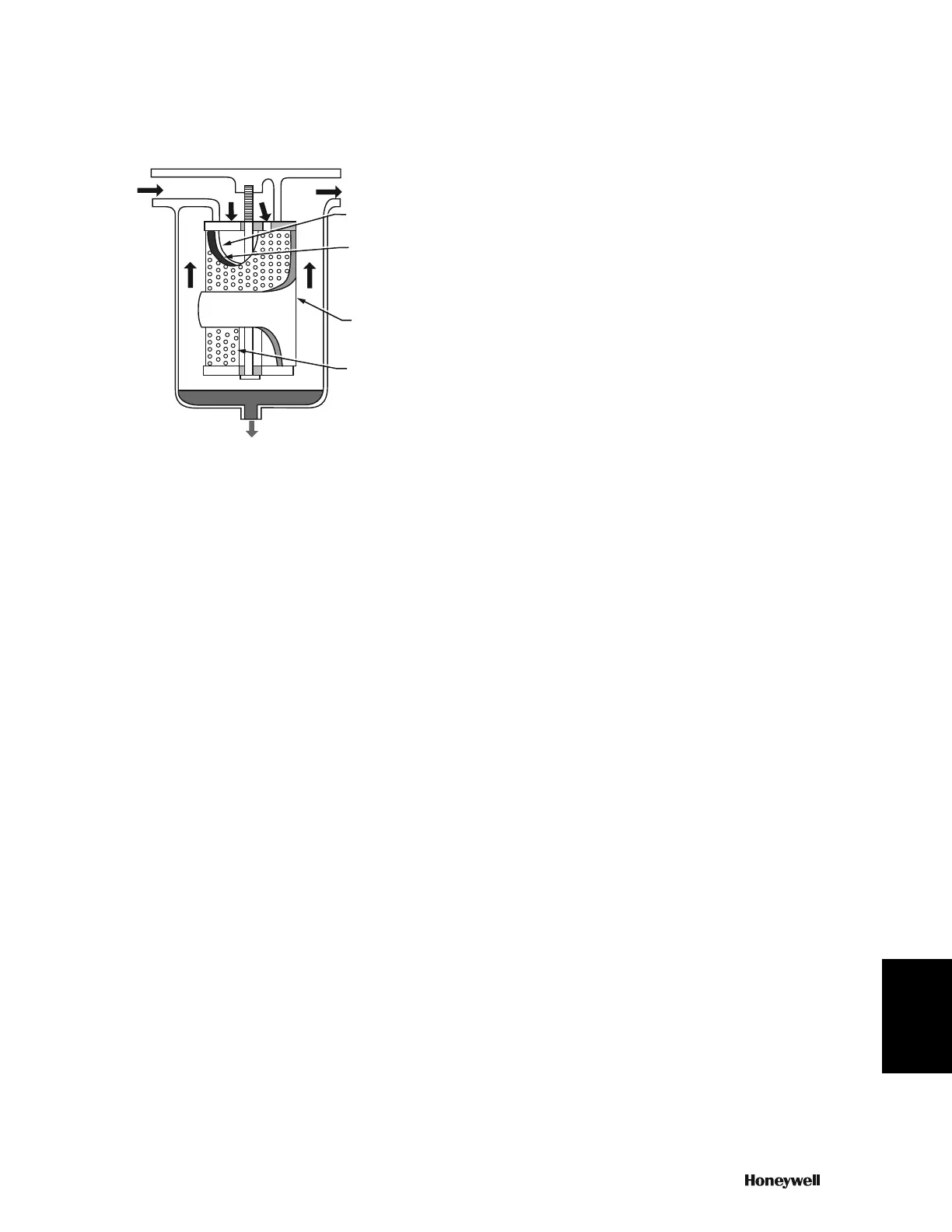
The air filter (Fig. 16) removes solid particulate matter and oil
aerosols or mist from the control air.
Fig. 16. Typical Air Filter.
Oil contamination in compressed air appears as a gas or an
aerosol. Gaseous oil usually remains in a vapor state
throughout the system and does not interfere with operation of
the controls. Aerosols, however, can coalesce while flowing
through the system, and turbulence can cause particles to
collect in device filters, orifices, and small passages.
Many filters are available to remove solids from the air.
However, only an oil-coalescing filter can remove oil aerosols
from control air. An oil coalescing filter uses a bonded fibrous
material to combine the small particles of oil mist into larger
droplets. The coalesced liquids and solids gravitate to the
bottom of the outer surface of the filter material, drop off into a
sump, and are automatically discharged or manually drained.
The oil coalescing filter continues to coalesce and drain off
accumulated oil until solid particles plug the filter. An increase in
pressure drop across the filter (to approximately 10 psi)
indicates that the filter element needs replacement. For very
dirty air, a 5-micron prefilter filters out large particles and
increases the life of the final filter element.
Pressure Reducing Valves
A pressure reducing valve station can have a single-pressure
reducing valve or a two-pressure reducing valve, depending on
the requirements of the system it is supplying.
SINGLE-PRESSURE REDUCING VALVE
After it passes though the filter, air enters the PRV (Fig. 11).
Inlet pressure ranges from 60 to 150 psi, depending on tank
pressures maintained by the compressor. Outlet pressure is
adjustable from 0 to 25 psi, depending on the control air
requirements. The normal setting is 20 psi.
A safety relief valve is built into some PRV assemblies to
protect control system devices if the PRV malfunctions. The
valve is typically set to relieve downstream pressures above
24 psi.
TWO-PRESSURE REDUCING VALVE
A two-pressure reducing valve is typically set to pass 13 or 18
psi to the control system, as switched by a pilot pressure. The
two-pressure reducing valve is the same as the single-pressure
reducing valve with the addition of a switchover diaphragm and
switchover inlet to accept the switchover pressure signal.
Switchover to the higher setting occurs when the inlet admits
main air into the switchover chamber. Exhausting the
switchover chamber returns the valve to the lower setting.
The switchover signal is typically provided by an E/P relay or a
two-position diverting switch. An automatic time clock can
operate an E/P relay to switch the main pressure for a
day/night control system. A diverting switch is often used to
manually switch a heating/cooling system.
In many applications requiring two-pressure reducing valves, a
single-pressure reducing valve is also required to supply single-
pressure controllers which do not perform well at low pressures.
Higher dual pressure systems operating at 20 and 25 psi are
sometimes used to eliminate the need and expense of the
second PRV.
THERMOSTATS
Thermostats are of four basic types:
— A low-capacity, single-temperature thermostat is the basic
nozzle-flapper bleed-type control described earlier. It is a
bleed, one-pipe, proportional thermostat that is either direct
or reverse acting.
— A high-capacity, single-temperature thermostat is a low
capacity thermostat with a capacity amplifier added. It is a
pilot-bleed, two-pipe, proportioning thermostat that is either
direct or reverse acting.
— A dual-temperature thermostat typically provides occupied/
unoccupied control. It is essentially two thermostats in one
housing, each having its own bimetal sensing element and
setpoint adjustment. A valve unit controlled by mainline
pressure switches between the occupied and unoccupied
mode. A manual override lever allows an occupant to
change the thermostat operation from unoccupied operation
to occupied operation.
— A dual-acting (heating/cooling) thermostat is another two-
pipe, proportioning thermostat that has two bimetal sensing
elements. One element is direct acting for heating control,
and the other, reverse acting for cooling control. Switchover
is the same as for the dual-temperature thermostat but
without manual override.
Other thermostats are available for specific uses. Energy
conservation thermostats limit setpoint adjustments to
reasonable minimums and maximums. Zero energy band
thermostats provide an adjustable deadband between heating
and cooling operations.
The thermostat provides a branchline air pressure that is a
function of the ambient temperature of the controlled space and
the setpoint and throttling range settings. The throttling range
setting and the setpoint determine the span and operating
range of the thermostat. The nozzle-flapper-bimetal assembly
maintains a fixed branchline pressure for each temperature
within the throttling range (Fig. 17). The forces within the
nozzle-flapper-bimetal assembly always seek a balanced
IR IN
AIR OUT
INNER FOAM
SLEEVE
FILTERING
MEDIUM
OUTER FOAM
SLEEVE
PERFORATED
METAL
CYLINDER
LIQUID DRAIN
C2601
 Loading...