Pneumatic Control System Example
156 customer.honeywell.com 70-6925
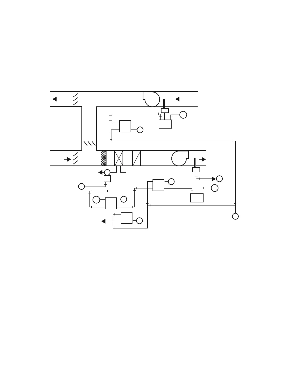
Warm-Up/Heating Coil Control Sequence
Any time the Supply Fan (Fig. 78) runs and the return air
temperature is below 69F, Temperature Controller TC-1 trips
Snap-Acting Relay SA-1 to position Switching Relays SR-1 and
SR-2 to initialize warm-up control. Relay SA-1 also positions
Switching Relay SR-4 to disable cooling controls. Switching
Relay SR-2 opens all interior VAV box dampers and starts the
hot water pump. Relay SR-1 switches the hot water valve from
normal control to warm-up control via Controller TC-2 and
modulates the hot water valve to maintain a discharge air
temperature setpoint of 90F.
NOTE: Fan powered perimeter VAV boxes are cool in this
mode and operate with the fans on and at the mini-
mum airflow (warm air) setpoints. Reheat valves at
each box operate as needed. This allows the warm-up
cycle to operate the air handling unit (AHU) fans at a
reduced and low cost power range.
Fig. 78. Heating Coil Control.
M
M
Y
2
EP
2
EP
M
Z
X
P
CX
O
P
CX
O
M
P
CX
O
P
CX
O
SR-1
SR-3
SR-2
RA
70
BSM
TC-1
2
EP
DA
90
BSM
TC-2
SA-1
C-X < 69
C-O >71
SNAP
ACTING
RELAY
RETURN
AIR
RETURN FAN
OUTSIDE
AIR
TO COOLING
CONTROLS
TS-1
FROM
COOLING
CONTROLS
3-8 PSI N.O.
SIGNAL TO OPEN
ALL INTERIOR VAV
BOX DAMPERS AND
START HOT WATER PUMP
M10301
TO
COOLING
CONTROLS
SUPPLY FAN
AIR DURING COLD RETURN AIR (WARM-UP)
 Loading...