Valves
Humidistats
and
Thermostats Controllers Sensors Relays Switches Actuators Valves Accessories
Engineering
Guide
Cross
Reference
70-6925 105
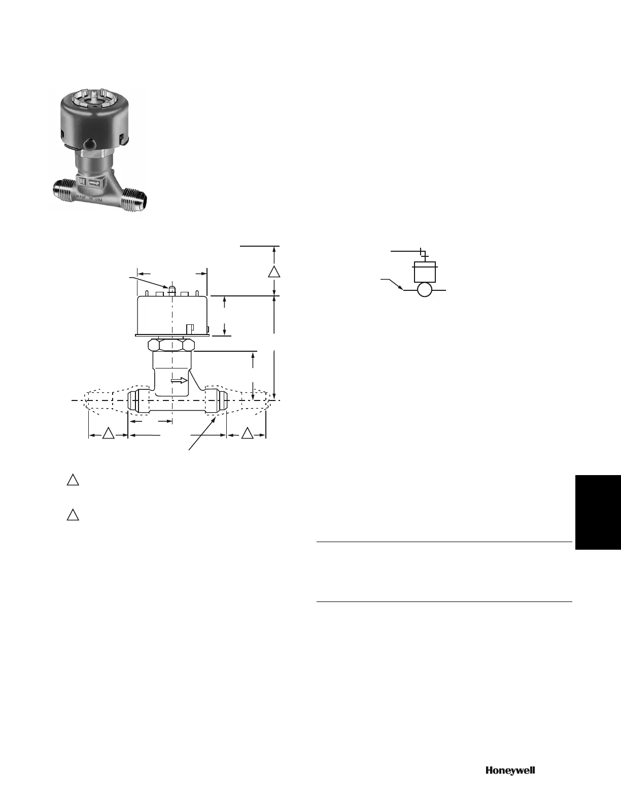
VP527 Pneumatic Water Valve
Normally open, single-seated, high pressure valve provides
proportional control of hot and/or cold water in unit air
conditioners and fan coil units. Replacement devices are available
for Johnson, Powers, Robertshaw, Barber-Colman, and older
Honeywell devices.
• Small size permits installation where space is limited.
• Forged brass, straight-through body with end connections threaded
for 45 degrees SAE flare fitting nuts.
• Spring-loaded, self-adjusting, Buna-N “V”-ring packing is
replaceable without shutting system down.
• High-temperature rolling diaphragm actuator (aluminum cover) and
high-temperature plastic diaphragm retaining cup with integral air
connection for 1/4 in. (6 mm) O.D. plastic tubing.
• Integral seat and brass plug with removable composition disc
provides equal percentage flow.
• Stainless steel stem, 3/16 in. (5 mm) diameter.
Dimensions in inches (millimeters) VP527 Typical Piping Diagram
Valve Type: Unitary
Body Pattern: Two-way
Body Pressure: 250 psi (1724 kPa)
Air Connections: Push on for 1/4 in. O.D. plastic tubing
Valve Action: Proportional Normally Open
Controlled Medium: Water
Type of End Connection: 45 deg. SAE flare
Operating Humidity Range (% RH): 5 to 95% RH
Temperature Range: 35 F to 250 F (2 C to 121 C)
Maximum Safe Actuator Diaphragm Temperature: 230 F (110 C)
Maximum Diaphragm Pressure: 30 psi (205 kPa)
Accessories:
14003648-001 Vandalism Resistant Assembly, Cover assembly with 1/
8 in NPT air Connection and push-in retainer to replace standard
Cover
14004932-001 Pneumatic Valve Adapter (M6410/M7410 linkage and a
green main spring to allow to retrofit an electric actuator)
Replacement Parts:
14003102-001 Replacement top assembly
14003297-001 Valve repack kit for VP526A, VP527A, or VP531A
valves with 3/16 inch stem
14003475-001 Valve Rebuild Kit for 1/2 in. valve with 0.4 or 0.63 Cv
14003476-001 Valve Rebuild Kit for 1/2 in. valve with 1 or 1.6 Cv
315917 Diaphragm
1
22
1 ALLOW 1-1/2 IN. (38 MM) MINIMUM CLEARANCE TO SERVICE VALVE,
2-1/2 IN. (63 MM) CLEARANCE TO CONNECT TUBING STRAIGHT TO
CONNECTOR. IF CLEARANCE IS LESS THAN 2-1/2 IN. (63 MM),
USE AN ELBOW CONNECTOR.
2 ALLOW 1-3/8 IN. (35 MM) MINIMUM CLEARANCE TO REMOVE VALVE.
M18348A
2-1/4 (57) DIA.
IR CONNECTION
FOR 1/4 IN. (6 MM)
O.D. PLASTIC TUBING
1-1/2
(38)
3-13/16
(97)
1-5/8
(41)
3-1/8 (79)
1-3/8
(35)
1/2 IN. (12MM) X 45 SAE FLARED TUBE
CONNECTION - 2 (NOT FURNISHED)
CONTROL
AIR
HOT OR CHILLED
WATER SUPPLY
VP527A
N.O.
C5514
 Loading...