Basic Pneumatic Control System
70-6925 127
Humidistats
and
Thermostats Controllers Sensors Relays Switches Actuators Valves Accessories
Engineering
Guide
Cross
Reference
heating or cooling, the water pressure, and the control and flow
characteristics required. An actuator is then selected to operate
the final control element. A controller and relays complete the
system. When all control systems for a building are designed,
the air supply system can be sized and designed.
Air Supply and Operation
The main line air supply is provided by an electrically driven
compressor pumping air into a storage tank at high pressure
(Fig. 2). A pressure switch turns the compressor on and off to
maintain the storage tank pressure between fixed limits. The
tank stores the air until it is needed by control equipment. The
air dryer removes moisture from the air, and the filter removes
oil and other impurities. The pressure reducing valve (PRV)
typically reduces the pressure to 18 to 22 psi. For two-pressure
(day/night) systems and for systems designed to change from
direct to reverse acting (heating/cooling), the PRV switches
between two pressures, such as 13 and 18 psi. The maximum
safe air pressure for most pneumatic controls is 25 psi.
Fig. 2. Compressed Air Supply System.
From the PRV, the air flows through the main line to the
controller (in Figure 1, a thermostat) and to other controllers or
relays in other parts of the system. The controller positions the
actuator. The controller receives air from the main line at a
constant pressure and modulates that pressure to provide
branchline air at a pressure that varies according to changes in
the controlled variable, as measured by the sensing element.
The controller signal (branchline pressure) is transmitted via the
branchline to the controlled device (in Figure 1, a valve
actuator). The actuator drives the final control element (valve)
to a position proportional to the pressure supplied by the
controller.
When the proportional controller changes the air pressure to
the actuator, the actuator moves in a direction and distance
proportional to the direction and magnitude of the change at the
sensing element.
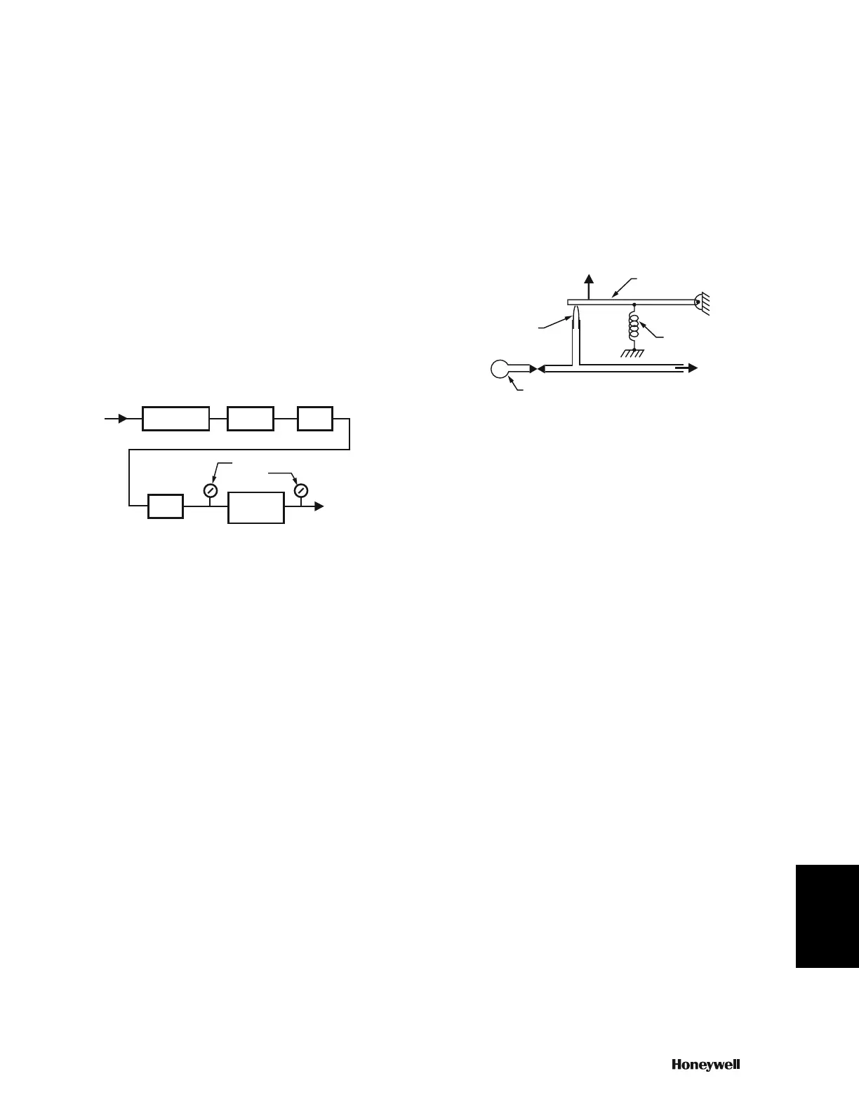
Restrictor
The restrictor is a basic component of a pneumatic control
system and is used in all controllers. A restrictor is usually a
disc with a small hole inserted into an air line to restrict the
amount of airflow. The size of the restrictor varies with the
application, but can have a hole as small as 0.003 inches.
Nozzle-Flapper Assembly
The nozzle-flapper assembly (Fig. 3) is the basic mechanism
for controlling air pressure to the branchline. Air supplied to the
nozzle escapes between the nozzle opening and the flapper. At
a given air supply pressure, the amount of air escaping is
determined by how tightly the flapper is held against the nozzle
by a sensing element, such as a bimetal. Thus, controlling the
tension on the spring also controls the amount of air escaping.
Very little air can escape when the flapper is held tightly against
the nozzle.
Fig. 3. Nozzle-Flapper Assembly with Restrictor.
To create a branchline pressure, a restrictor (Fig. 3) is required.
The restrictor and nozzle are sized so that the nozzle can
exhaust more air than can be supplied through the restrictor
when the flapper is off the nozzle. In that situation, the
branchline pressure is near zero. As the spring tension
increases to hold the flapper tighter against the nozzle,
reducing the air escaping, the branchline pressure increases
proportionally. When the spring tension prevents all airflow from
the nozzle, the branchline pressure becomes the same as the
mainline pressure (assuming no air is flowing in the branchline).
This type of control is called a “bleed” control because air
“bleeds” continuously from the nozzle.
With this basic mechanism, all that is necessary to create a
controller is to add a sensing element to move the flapper as
the measured variable (e.g., temperature, humidity, pressure)
changes. Sensing elements are discussed later.
Pilot Bleed System
The pilot bleed system is a means of increasing air capacity as
well as reducing system air consumption. The restrictor and
nozzle are smaller in a pilot bleed system than in a nozzle
flapper system because in a pilot bleed system they supply air
only to a capacity amplifier that produces the branchline
pressure (Fig. 4). The capacity amplifier is a pilot bleed
component that maintains the branchline pressure in proportion
to the pilot pressure but provides greater airflow capacity.
AIR
SUPPLY
IN
AIR
COMPRESSOR
STORAGE
TANK
AIR
DRYER
FILTER
PRESSURE
GAGES
PRESSURE
REDUCING
VALVE
MAIN AIR TO
PNEUMATIC
CONTROL
SYSTEM
C2616-1
M
SENSOR
FORCE
FLAPPER
SPRING
BRANCH
RESTRICTOR
AIR SUPPLY
NOZZLE
C1084
 Loading...