Pneumatic Control Combinations
150 customer.honeywell.com 70-6925
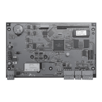
Fig. 66. Two-Pressure Main Supply System
with Automatic Changeover.
Compensated Control System
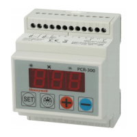
In a typical compensated control system (Fig. 67), a dual-input
controller increases or decreases the temperature of the supply
water as the outdoor temperature varies. In this application, the
dual-input controller resets the water temperature setpoint as a
function of the outdoor temperature according to a preset
schedule. The system then provides the scheduled water
temperature to the convectors, fan-coil units, or other heat
exchangers in the system.
Fig. 67. Compensated Supply Water System
Using Dual-Input Controller.
Electric-Pneumatic Relay Control
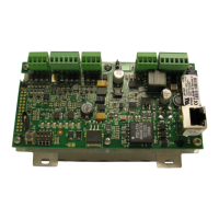
Figure 68 shows one use of an E/P relay in a pneumatic control
circuit. The E/P relay connects to a fan circuit and energizes
when the fan is running and de-energizes when the fan turns
off, allowing the outdoor air damper to close automatically when
the fan turns off. The relay closes off the controller branchline,
exhausts the branchline going to the damper actuator, and
allows the damper to go to its normal (closed) position. Figure
69 shows an E/P relay application that shuts down an entire
control system.
Fig. 68. Simple E/P Relay Combination.
Fig. 69. E/P Relay Combination for System Shutdown.
Pneumatic-Electric Relay Control
A P/E relay provides the interlock when a pneumatic controller
actuates electric equipment. The relays can be set for any
desired pressure. Figure 70 shows two P/E relays sequenced
to start two fans, one at a time, as the fans are needed.
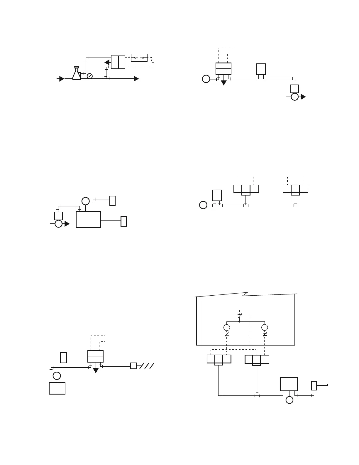
Fig. 70. P/E Relays Controlling Fans in Sequence.
On a rise in temperature, Relay 1 puts Fan 1 in operation as the
thermostat branchline pressure reaches 7 psi. Relay 2 starts
Fan 2 when the controller branchline pressure reaches 12 psi.
On a decrease in branchline pressure, Relay 2 stops Fan 2 at
10 psi branchline pressure, and Relay 1 stops Fan 1 at 5 psi
branchline pressure.
Figure 71 shows two spdt P/E relays starting and stopping a
two-speed fan to control condenser water temperature.
Fig. 71. Two-Speed Fan Operated by P/E Relays.
FROM
COMPRESSOR
TWO-PRESSURE
REDUCING VALVE
X = NORMALLY DISCONNECTED
O = NORMALLY CONNECTED
EXH
MAIN
AIR
C2376
C
O
X
ELECTRIC
POWER
THERMOSTAT
OR TIME CLOCK
E/P RELAY
GAUGE
M
VALVE
HOT WATER SUPPLY
TEMPERATURE
SENSOR
OUTDOOR AIR
TEMPERATURE
SENSOR
CONTROLLER
B M S
1
S
2
C2356
EXH
M
XOC
MIXED AIR
SENSOR
BMS
FAN
VOLTAGE
E/P
RELAY
N.C. DAMPER
ACTUATOR
N.C. DAMPER
C2361
DA CONTROLLER
C2358
EXH
N.C.
VALVE
THERMOSTAT
M
B
M
XO
C
SYSTEM
INTERLOCK
VOLTAGE
E/P RELAY
THERMOSTAT
M
B
M
C N.C. N.O.
WIRED TO
START FAN 1
P/E RELAYS
SET
5-7 PSI
SET
10-12 PSI
C N.C. N.O.
WIRED TO
START FAN 2
C2359
M
B M S
C N.C.
N.O.
DA
CONTROLLER
P/E RELAY 2
SET 12-14 PSI
C N.C.
N.O.
COOLING TOWER
FAN STARTER
CONTROL VOLTAGE
OVERLOAD
LOW SPEED
HIGH AUXILIARY
LOW AUXILIARY
HIGH SPEED
FAN STARTER
P/E RELAY 1
SET 7-9 PSI
SENSOR IN
CONDENSER
WATER
C2367
 Loading...