Relays and Switches
140 customer.honeywell.com 70-6925
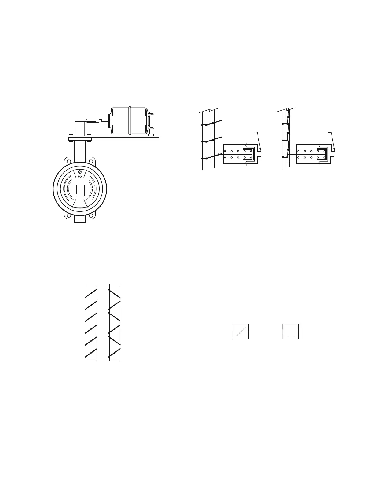
Two- and three-way butterfly valves can be operated by long
stroke pneumatic actuators and appropriate linkage (Fig. 31).
One or two low pressure actuators powered directly by
branchline pressure can operate butterfly valves up to about 12
inches, depending on the differential close-off rating of the
valve. For other applications high pressure pneumatic cylinders
can be used to provide the force required by the valve. A
pneumatic positioner provides an appropriate high pressure
signal to the cylinder based on a 3 to 15 psi input signal.
Fig. 31. Butterfly Valve Assembly.
Dampers
Dampers control the flow of air in air-handling systems. The
most common type of damper, a multiblade louver damper, can
have parallel or opposed blades (Fig. 32).
Fig. 32. Parallel- and Opposed-Blade Dampers.
Figure 33 shows normally open and normally closed parallel-
blade dampers. A normally open damper returns to the open
position with low air pressure in the actuator diaphragm
chamber. An increase in branchline pressure forces the rolling
diaphragm piston to move against the spring, and a decrease
allows the compressed spring to force the piston and
diaphragm back to the normal position. As with valve actuators,
intermediate positions depend on a balance between the force
of the control air pressure on the diaphragm and the opposing
force of the actuator spring.
Fig. 33. Normally Open and Normally Closed Dampers.
A normally closed damper returns to the closed position with
low air pressure in the actuator diaphragm chamber. The way
the damper blades, crank arm, and push rod are oriented
during installation determines the normal (open or closed)
position of the damper blades.
For a more detailed discussion of dampers, see the DAMPER
SELECTION AND SIZING section.
RELAYS AND SWITCHES
In the following illustrations, common (C) and the normally
connected port (O) are connected on a fall in pilot pressure (P)
below the relay setpoint, and the normally disconnected port (X)
is blocked (Fig. 34). On a rise in pilot pressure above the relay
setpoint, C and X are connected and O is blocked.
Fig. 34. Relay Port Connections.
M10403
PARALLEL
BLADES
OPPOSED
BLADES
C2604
C2605
NORMALLY OPEN
DAMPER ASSEMBLY
BRANCH LINE
BRANCH LINE
ACTUATOR
NORMALLY CLOSED
DAMPER ASSEMBLY
ACTUATOR
PILOT SIGNAL BELOW
RELAY SETPOINT
PILOT SIGNAL ABOVE
RELAY SETPOINT
PORTS: P= PILOT
C= COMMON
O= NORMALLY CONNECTED
X= NORMALLY DISCONNECTED
C2344
PO
CX
PO
CX
 Loading...