Pneumatic Control Combinations
70-6925 149
Humidistats
and
Thermostats Controllers Sensors Relays Switches Actuators Valves Accessories
Engineering
Guide
Cross
Reference
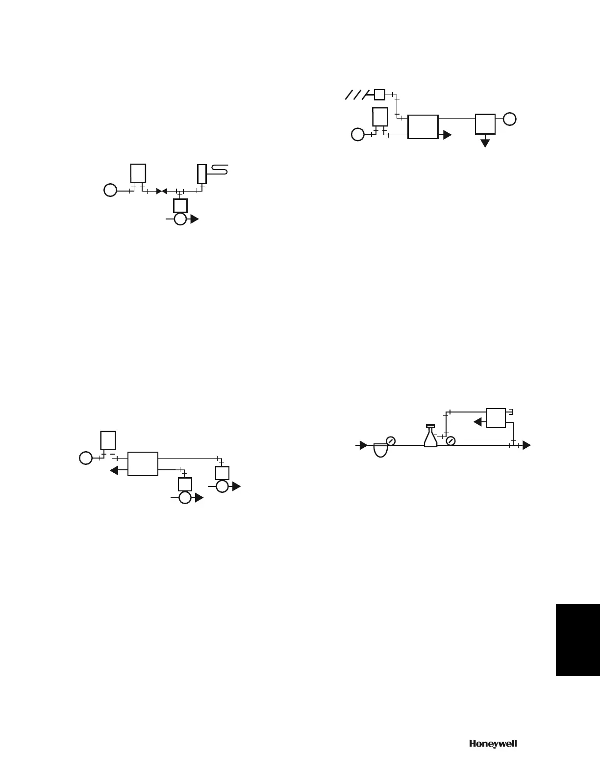
Bleed-type, low-limit controllers can be used with pilot-bleed
thermostats (Fig. 62). A restrictor installed between the
thermostat and the low-limit controller, allows the low limit
controller to bleed the branchline and open the valve. The
restrictor allows the limit controller to bleed air from the valve
actuator faster than the thermostat can supply it, thus overriding
the thermostat.
Fig. 62. Bleed-Type, Low-Limit Control System.
Manual Switch Control
Common applications for a diverting switch include on/off/
automatic control for a heating or a cooling valve, open/closed
control for a damper, and changeover control for a two-pressure
air supply system. Typical applications for a proportional switch
include manual positioning, remote control point adjustment,
and minimum damper positioning.
Figure 63 shows an application for the two-position manual
switch. In Position 1, the switch places the thermostat in control
of Valve 1 and opens Valve 2 by bleeding Valve 2 to zero
through Port 1. When turned to Position 2, the switch places the
thermostat in control of Valve 2 and Valve 1 opens.
Fig. 63. Application for Two-Position Manual Switch.
Figure 64 shows an application of the three-position switch and
a proportioning manual positioning switch.
Fig. 64. Application for Three-Position Switch and Manual
Positioning Switch.
In Position 1, the three-position switch places the thermostat in
control of the damper. Position 2 closes the damper by bleeding
air pressure to zero through Port 3. Position 3 allows the
manual positioning switch to control the damper.
Changeover Control For Two-Pressure Supply
System
Figure 65 shows a manual switch used for changeover from 13
to 18 psi in the mains. Either heating/cooling or day/night
control systems can use this arrangement. In Position 1, the
switch supplies main pressure to the pilot chamber in the PRV.
The PRV then provides 18 psi (night or heating) main air
pressure to the control system.
Fig. 65. Two-Pressure Main Supply System
with Manual Changeover.
In Position 2, the manual switch exhausts the pilot chamber in
the PRV. The PRV then provides 13 psi (day or cooling) to the
system.
Figure 66 shows a two-pressure system with automatic
changeover commonly used in day/night control. A switch in a
seven-day time clock and an E/P relay provide the changeover.
When the E/P relay energizes (day cycle), the pilot chamber in
the PRV exhausts and controls at 13 psi. When the electric-
pneumatic relay de-energizes, the pilot chamber receives full
main pressure and the PRV provides 18 psi air.
M
M
B
DA
THERMOSTAT
N.O. VALVE
C2350
DA
LOW-LIMIT
CONTROLLER
M
M
B
THERMOSTAT
C2351
3
1
4
2
EXH
TWO-POSITION
SWITCH
N.O. VALVE 1
N.O. VALVE 2
NOTE:
POSITION 1: PORTS 3 AND 2, 1 AND 4 CONNECTED
POSITION 2: PORTS 3 AND 4, 1 AND 2 CONNECTED
M
M
B
DA
THERMOSTAT
C2352
THREE-POSITION
SWITCH
NOTE: POSITION 1: AUTOÑPORTS 2 AND 4 CONNECTED
POSITION 2: CLOSEDÑPORTS 2 AND 3 CONNECTED
POSITION 3: MANUALÑPORTS 2 AND 1 CONNECTED
DAMPER
ACTUATOR
M
2
4
1
3
EXH
B
E
M
EXH
MANUAL
POSITIONING
SWITCH
13
24
CAP
HIGH PRESSURE
GAGE
FROM
COMPRESSOR
FILTER
TWO-PRESSURE
REDUCING VALVE
EXH
MANUAL
SWITCH
MAIN PRESSURE
GAUGE
MAIN
AIR
C2375
 Loading...