34 XLS140 Installation Manual Form Number 95-7673-3 P/N 51927:C 12/06/2005
Installation Installing the Control Panel
2. Screw chassis to the backbox.
3. Attach XLS140-CPU to the chassis. Slide control-panel tabs into slots on chassis and lay the
board onto stand-offs so that mounting holes line up with those on the chassis. Secure with
six (6) screws (four across the top of the board, and two to the left of the power supply)
provided with the chassis. (See Figure 3.4.)
4. If installing KDM-2, install the stand-offs included with the keyboard kit. (See Figure 3.4.)
• The upper edge of the keyboard mounting plate rests on two stacked pairs of male-female
stand-offs. Connect P/N 42185 (2.0 inch, 50.8 mm) to P/N 42186 (1.312 inch, 33.33 mm).
• Thread the stacked pairs of stand-offs through mounting holes on the control panel as shown in
Figure 3.4.
• Thread two P/N 42166 (0.937 inch, 23.8 mm) male-female stand-offs through mounting holes
in the chassis rail.
• Attach ribbon cable from keypad to J4 connector on control panel. (See Figure 2.3.)
• Align the keypad with the stand-offs and screw it down.
5. If using the XLS-NCA instead of the KDM-2, refer to Section 3.5.2 “Using XLS-NCA as
Primary Display” and the XLS-NCA Installation Manual.
6. If not using an LEM-320, secure the last 4 mounting holes with screws.
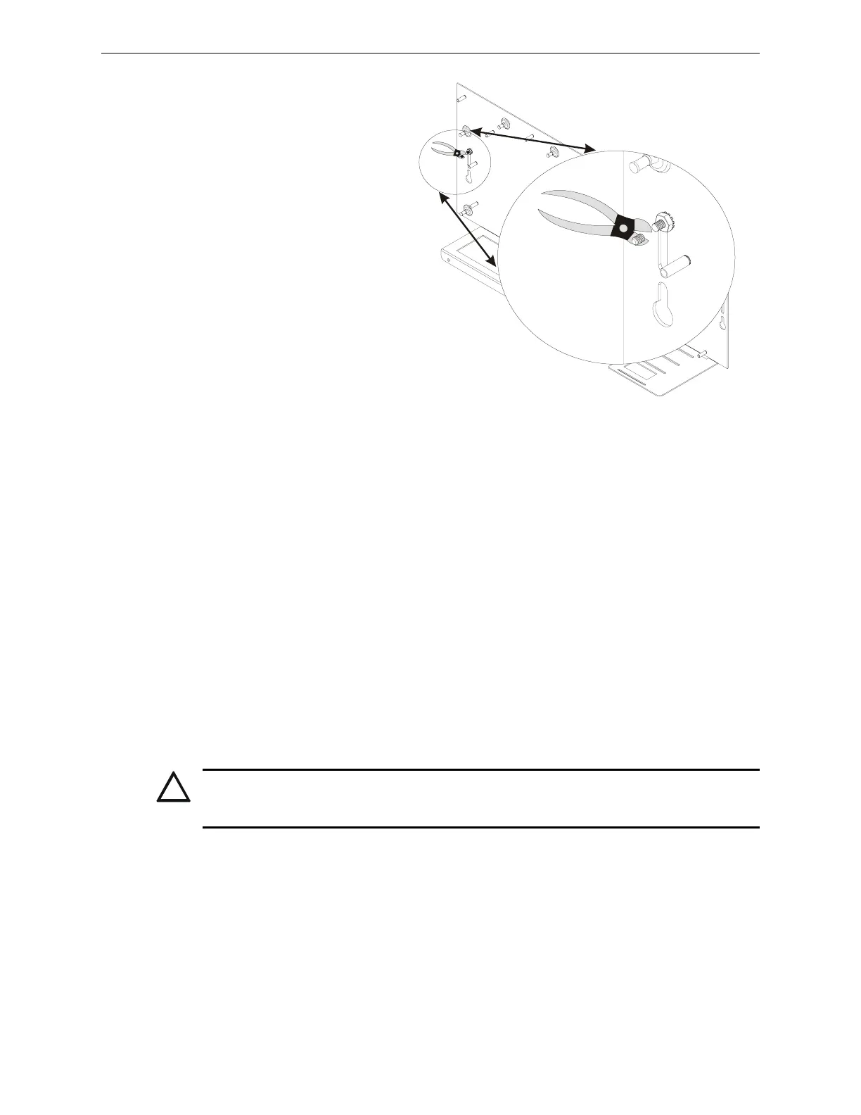
If using a new CHS-M2 in a CAB-3
series backbox or in a CAB-4 series
backbox manufactured before October
2002, verify stud height and cut any stud
that exceeds 0.375 in. (9.525 mm) as
per Step 1 above if a CPU is being
mounted above it. Reinstall electronics
as discussed in the steps below.
CHS-M2-11-03-CAB-3.wmf
Figure 3.3 Using the Redesigned CHS-M2 with Older Backboxes
!
CAUTION:
It is critical that all mounting holes of the XLS140 are secured with a screw or standoff to insure
continuity of Earth Ground.

 Loading...


