80 XLS140 Installation Manual Form Number 95-7673-3 P/N 51927:C 12/06/2005
Electrical Specifications Wire Requirements
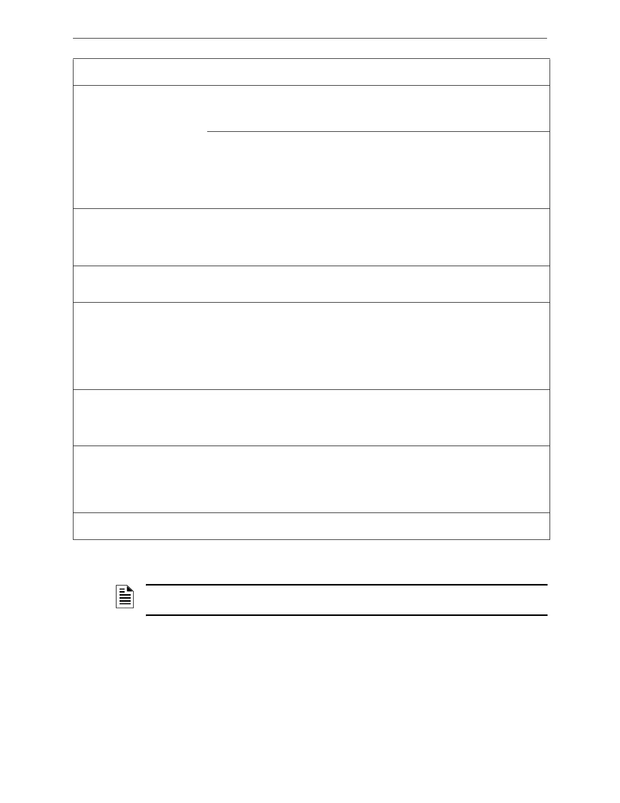
Circuit Type
Circuit
Function
Wire Requirements
Distance
(feet/meters)
Typical Wire Type
*
SLC
(power limited)
Connects to
intelligent and
addressable
modules.
Twisted-unshielded pair, 12 to 18 AWG
(3.31 to 0.82 mm
2
). 50 ohms maximum per
length of Style 6 & 7 loops. 50 ohms per
branch maximum for Style 4 loop.
12,500 ft. (3,810 m)
9,500 ft. (2,895.6 m)
6,000 ft. (1,828.8 m)
3,700 ft. (1,127.76 m)
12 AWG (3.31 mm
2
)
14 AWG (2.08 mm
2
)
16 AWG (1.31 mm
2
)
18 AWG (0.82 mm
2
)
or Untwisted, unshielded wire, in conduit or
outside of conduit.
Note: Maximum total capacitance of all
SLC wiring (both between conductors and
from any conductor to ground) should not
exceed 0.5 mircofarads.
1,000 ft. (304.8 m) 12 to 18 AWG (3.31 to
0.82 mm
2
)
EIA-485
(power limited)
Connects to
XLS-LCD-80,
ACS modules,
or TM-4
Transmitter
Twisted-shielded pair with a characteristic
impedance of 120 ohms. 18 AWG (0.82
mm
2
) minimum.
6,000/1829
(max)
16 AWG (1.31 mm
2
)
EIA-232
(power limited)
Connects to
Printers, CRT,
or PC.
Twisted-shielded pair in conduit.
18 AWG (0.82 mm
2
) minimum.
50/15.24
(without modem)
16 AWG (1.31 mm
2
)
IDC
Initiating Device
Circuit
XLS-MM-A/
TC809A1059,
XLS-MM-B/
TC809B1008,
XP5-M,
XP10-M,
XP6-MA
(power limited)
12-18 AWG (3.31 to 0.82 mm
2
).
Maximum circuit resistance is 20 ohms.
12 to 18 AWG (3.31 to
0.82 mm
2
)
NAC
Notification
Appliance
Circuit
XLS-CM-N/
TC810N1013,
XP6-C (power
limited)
12-18 AWG (3.31 to 0.82 mm
2
).
At alarm current level, no more than a 1.2
V drop at the end of the circuit, or sized to
provide the minimum rated operating
voltage of the appliances used.
To meet 1.2 V drop,
or sized to provide
the minimum rated
operating voltage of
the appliances used.
12 to 18 AWG (3.31 to
0.82 mm
2
)
24 VDC Power
Runs
(power-limited)
To T M -4
Transmitter,
Annunciator and
XLS-CM-N/
TC810N1013
modules
12-18 AWG (3.31 to 0.82 mm
2
).
Size wire so that no more than 1.2 V drop
across wire run from supply source to end
of any branch.
To meet 1.2 volt drop 12 to 18 AWG (3.31 to
0.82 mm
2
)
CHG-120 External battery
charger
12 AWG (3.31 mm
2
) in conduit 20/6.1 (max) 12 AWG (3.31 mm
2
)
Table B.1 Wire Requirements
* Notifier brand cable is recommended; see the product catalog available from Paige Electric.
NOTE: Lightning arresters required on circuits extending between buildings; 999 meter length
maximum to meet UL 1459.

 Loading...


