Data
Communications
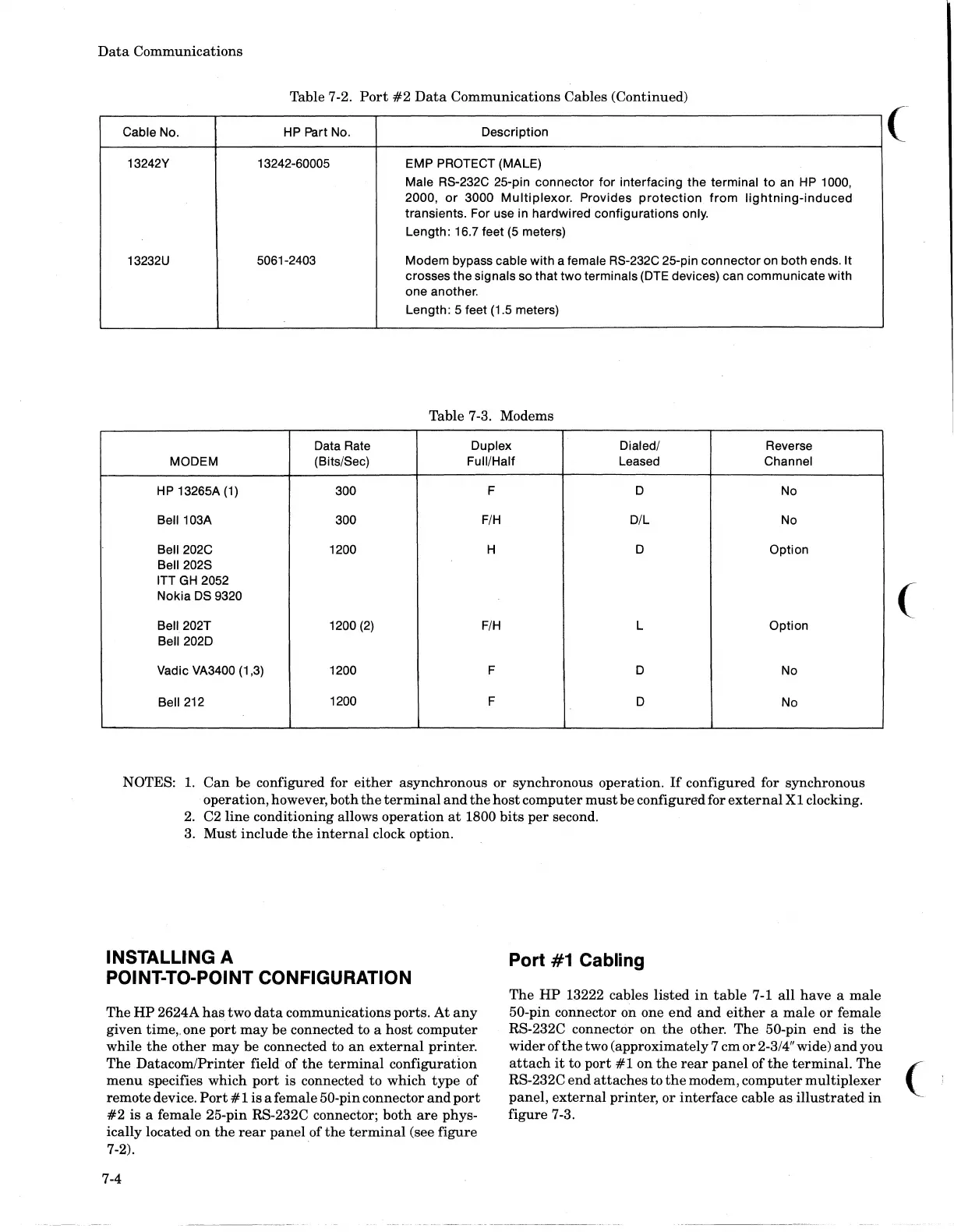
Table 7-2.
Port
#2
Data
Communications Cables (Continued)
Cable No.
HP
Part No.
Description
13242Y 13242-60005 EMP
PROTECT (MALE)
Male RS-232C 25-pin connector
for
interfacing the terminal
to
an
HP
1000,
2000,
or
3000 Multiplexor. Provides
protection
from
lightning-induced
transients. For use in hardwired configurations only.
Length: 16.7 feet
(5
meters)
13232U
5061-2403 Modem bypass
cable with a female RS-232C 25-pin connector on both ends. It
crosses the signals so that two terminals
(DTE
devices) can communicate with
one another.
Length: 5 feet (1.5 meters)
Table 7-3. Modems
Data Rate Duplex Dialed/ Reverse
MODEM (Bits/Sec) Full/Half Leased Channel
HP
13265A
(1)
300
F D
No
Bell103A 300
F/H
D/L
No
Bell202C
1200
H D
Option
Bell202S
ITT
GH
2052
Nokia
DS
9320
Bell202T
1200
(2)
F/H
L Option
Bell202D
Vadic VA3400 (1,3) 1200 F D
No
Bell
212
1200
F
D
No
NOTES:
1.
Can
be
configured for
either
asynchronous
or
synchronous operation.
If
configured for synchronous
operation, however,
both
the
terminal
and
the
host
computer
must
be configured for
external
Xl
clocking.
2. C2
line
conditioning allows
operation
at
1800
bits
per
second.
3.
Must
include
the
internal
clock option.
INSTALLING A
POINT-lO-POINT CONFIGURATION
Port
#1
Cabling
The
HP
13222 cables
listed
in
table
7-1
all
have
a
male
50-pin connector on one
end
and
either
a
male
or
female
RS-232C connector on
the
other. The 50-pin
end
is
the
wider of
the
two (approximately 7
cm
or
2-3/4" wide)
and
you
(
The
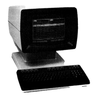
HP
2624A
has
two
data
communications ports.
At
any
given time" one
port
may
be connected to a
host
computer
while
the
other
may
be
connected to
an
external
printer.
The
Datacom/Printer
field
of
the
terminal
configuratIon
menu
specifies which
port
is connected to which
type
of
remote device.
Port
# 1 is a female 50-pin connector
and
port
#2
is
a female 25-pin RS-232C connector;
both
are
phys-
ically located on
the
rear
panel
of
the
terminal
(see
figure
attach
it
to
port
#1
on
the
rear
panel
of
the
terminal.
The (
RS-232C
end
attaches
to
the
modem, computer
multiplexer
panel,
external
printer,
or
interface
cable
as
illustrated
in
-
figure
7-3.
7-2). .
7-4