412
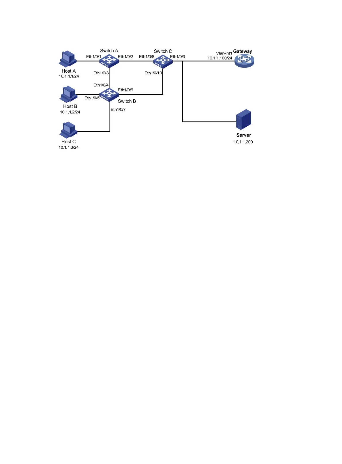
Figure 133 Network diagram
Configuration procedure
1. Configure IP addresses of the hosts, as in shown in Figure 133.
2. Configure the IP address of VLAN-interface 1 on the gateway.
<Gateway> system-view
[Gateway] interface Vlan-interface 1
[Gateway-Vlan-interface1] ip address 10.1.1.100 24
3. Configure Switch A:
# Enable STP.
[SwitchA] stp enable
# Configure manual-mode MFF.
[SwitchA] vlan 100
[SwitchA-vlan-100] mac-forced-forwarding default-gateway 10.1.1.100
# Specify the IP address of the server.
[SwitchA-vlan-100] mac-forced-forwarding server 10.1.1.200
# Enable ARP snooping.
[SwitchA-vlan-100] arp-snooping enable
[SwitchA-vlan-100] quit
# Configure Ethernet 1/0/2 and Ethernet 1/0/3 as network ports.
[SwitchA] interface ethernet 1/0/2
[SwitchA-Ethernet1/0/2] mac-forced-forwarding network-port
[SwitchA-Ethernet1/0/2] quit
[SwitchA] interface ethernet 1/0/3
[SwitchA-Ethernet1/0/3] mac-forced-forwarding network-port
4. Configure Switch B:
# Enable STP.
[SwitchB] stp enable
# Configure manual-mode MFF.
[SwitchB] vlan 100
[SwitchB-vlan-100] mac-forced-forwarding default-gateway 10.1.1.100
# Specify the IP address of the server.
 Loading...


