Home
HP
Measuring Instruments
8712ET
HP 8712ET User Manual
4
of 1
of 1 rating
507 pages
Give review
Manual
Specs
To Next Page
To Next Page
To Previous Page
To Previous Page
Loading...
ES User’
s Guide
4-47
Using Instrument Functions
Customizing the Display
Enabling/Disabling Display F
eatures
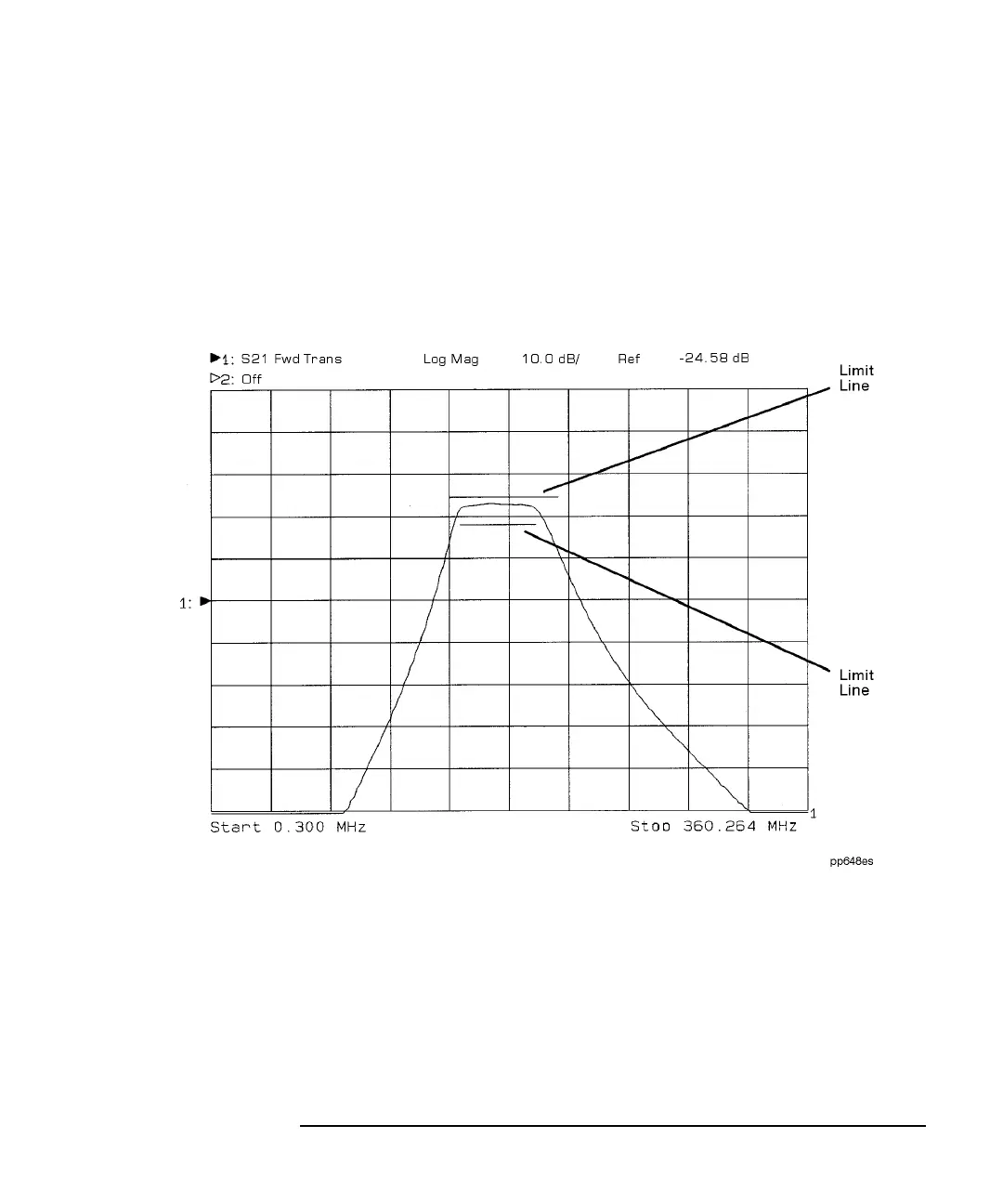
Figure 4-21
shows a display screen with graticule lines (the
measurement grid), and two limit lines. In the default or preset state
,
these lines are turned on.
Figure 4-21
Display F
eatures
180
182
Table of Contents
Default Chapter
9
Table of Contents
9
1 Installing the Analyzer
17
Introduction
18
Step 1. Check the Shipment
19
Step 2. Meet Electrical and Environmental Requirements
20
Step 3. Check the Analyzer Operation
25
Step 4. Configure the Analyzer
26
Connecting Peripherals and Controllers
27
Installing the Analyzer in a Rack
32
Preventive Maintenance
33
Clean the CRT
33
Check the RF Front Panel Connectors
33
2 Getting Started
35
Introduction
36
Front Panel Tour
37
Entering Measurement Parameters
38
Entering Frequency Range
40
Entering Source Power Level
40
Scaling the Measurement Trace
40
Viewing Measurement Channels
42
Performing the Operator's Check
44
Equipment List
44
Make S21 and S12 Transmission Measurements
45
Make a Broadband Power Measurement
47
Make S11 and S22 Reflection Measurements
48
If the Analyzer Fails the Operator's Check
51
3 Making Measurements
53
Introduction
54
Measuring Devices with Your Network Analyzer
55
The Measurement Display Icon
59
Measuring S-Parameters
61
Attenuation and Amplification in a Measurement Setup
63
When to Change the System Impedance
64
The Typical Measurement Sequence
65
Using the BEGIN Key to Make Measurements
66
BEGIN Key Overview
67
Using the BEGIN Key to Configure Measurements
68
AUTOST Files
70
The User BEGIN Function
70
Measuring S-Parameters Using a
71
Two-Port Calibration
71
Enter the Measurement Parameters
72
Perform a User Two-Port Calibration
72
View and Interpret the S-Parameter Measurement Results
92
Transmission Using an Enhanced Response Calibration
93
Enter the Measurement Parameters
94
Perform an Enhanced Response Calibration
94
Connect the DUT
97
View and Interpret the S21 Measurement Results
98
Measuring S11 Reflection Port 1 Using a One-Port Calibration
100
Enter the Measurement Parameters
101
Perform a User One-Port Calibration
101
Connect the DUT
104
View and Interpret the S11 Measurement Results
106
Making a Power Measurement Using Broadband Detection
108
Enter the Measurement Parameters
108
Perform a Normalization Calibration
109
Connect the DUT
110
View and Interpret the Power Measurement Results
111
Measuring Conversion Loss
113
Enter the Measurement Parameters
114
Perform a Normalization Calibration
114
Connect the DUT
116
View and Interpret the Conversion Loss Results
117
Making Measurements with the Auxiliary Input
119
Auxiliary Input Characteristics
120
Measuring Group Delay
121
Enter the Measurement Parameters
122
Perform a User Two-Port Calibration
123
Connect the DUT
123
View and Interpret the Group Delay Measurement Results
123
Measuring Impedance Using the Smith Chart
125
Enter the Measurement Parameters
126
Perform a User Two-Port Calibration
126
Connect the DUT
127
View and Interpret the Impedance Measurement Results
128
Measuring Impedance Magnitude
132
How the Reflection Measurement Works
132
How the Transmission Measurement Works
133
4 Using Instrument Functions
135
Introduction
136
Using Markers
137
To Activate Markers
139
To Turn Markers off
140
To Use Marker Search Functions
141
To Use Marker Math Functions
152
To Use Delta (∆) Marker Mode
158
To Use Other Marker Functions
160
To Use Polar Format Markers
161
To Use Smith Chart Markers
161
Using Limit Testing
162
To Create a Flat Limit Line
163
To Create a Sloping Limit Line
164
To Create a Single Point Limit
166
To Use Marker Limit Functions
166
To Use Relative Limits
170
Other Limit Line Functions
171
Additional Notes on Limit Testing
173
Using Reference Tracking
176
To Track the Peak Point
177
To Track a Frequency
178
Customizing the Display
179
Using the Split Display Feature
180
Enabling/Disabling Display Features
181
Modifying Display Annotation
182
Expanding the Displayed Measurement
186
Saving and Recalling Measurement Results
189
Saving Instrument Data
191
To Recall from a Floppy Disk or Internal Memory
194
Other File Utilities
197
To Use Directory Utilities
199
Formatting a Floppy Disk
201
Connecting and Configuring Printers and Plotters
202
Select a Compatible Plotter or Printer
202
Select an Appropriate Interface Cable
203
Connect the Printer or Plotter
204
Configure the Hardcopy Port
205
Define the Printer or Plotter Settings
207
Printing and Plotting Measurement Results
212
To Select the Copy Port
212
To Define the Output
213
Using a Keyboard
217
To Connect the Keyboard
217
To Use the Keyboard to Edit
218
Front Panel Control Using a Keyboard
218
Using an External VGA Monitor
221
Customizing Color on an External Monitor
221
Synchronizing and Positioning the Display
223
5 Optimizing Measurements
225
Introduction
226
Increasing Sweep Speed
227
Select the Appropriate Calibration Type
227
To Increase the Start Frequency
228
To Set the Sweep Time to AUTO Mode
228
To Widen the System Bandwidth
228
To Reduce the Amount of Averaging
229
To Reduce the Number of Measurement Points
229
To View a Single Measurement Channel
230
To Turn off Alternate Sweep
231
To Turn off Markers and Marker Tracking
231
To Turn off Spur Avoidance
232
To Avoid Frequency Bandcrossings by Minimizing the Span (HP 8714ES Only)
232
Increasing Network Analyzer Dynamic Range
233
To Increase the Receiver Input Power
233
To Reduce the Receiver Noise Floor
234
Reducing Trace Noise
236
To Activate Averaging for Reducing Trace Noise
236
To Change System Bandwidth for Reducing Trace Noise
236
To Eliminate Receiver Spurious Responses
237
Reducing Mismatch Errors
239
Reducing Mismatch Errors in a Reflection Measurement
239
Reducing Mismatch Errors in a Transmission Measurement
240
Reducing Mismatch Errors When Measuring both Reflection and Transmission
241
Compensating for Phase Shift in Measurement Setups
242
Port Extensions
242
Electrical Delay
244
Measuring Devices with Long Electrical Delay
245
6 Calibrating for Increased Measurement Accuracy
247
Introduction
248
Measurement Calibration Overview
249
The Calibration Reference Plane
253
Default Versus User-Defined Calibration
254
When to Use a Default Calibration
254
When to Perform a User-Defined Calibration
254
Calibration Choices
255
Retrieving Previous User-Defined Calibrations
258
Presetting the Analyzer: How Calibration Is Affected
259
To Perform a Normalization Calibration
260
To Perform a Transmission Calibration
261
To Perform a Reflection Calibration
265
To Perform a Conversion Loss Calibration
268
Calibration Kits
269
Selecting a Calibration Kit Stored in the Analyzer
269
Creating a User-Defined Calibration Kit
271
Saving and Recalling the Calibration
279
Saving the Calibration
279
Recalling the Calibration
280
7 Front/Rear Panel
281
Introduction
282
Connectors
283
BNC Connectors
284
Multi-Pin Connectors
287
RF Connectors
295
Display
296
Knob
298
Power Switch
299
Display Intensity Control
300
Disk Drive
301
Line Module
302
Power Cables
302
The Line Fuse
304
The Voltage Selector Switch
305
8 Hardkey/Softkey Reference
307
Introduction
308
Numeric Entries
309
Other manuals for HP 8712ET
User Guide Supplement
116 pages
Installation Note
7 pages
4
Based on 1 rating
Ask a question
Give review
Questions and Answers:
Need help?
Do you have a question about the HP 8712ET and is the answer not in the manual?
Ask a question
HP 8712ET Specifications
General
Brand
HP
Model
8712ET
Category
Measuring Instruments
Language
English
Related product manuals
HP 8712ES
507 pages
HP 8712C
559 pages
HP 8711C
530 pages
HP 8719ET
283 pages
HP 8753D
678 pages
HP 8756A
68 pages
HP 8753E
612 pages
HP 8753D Option 011
398 pages
HP 8901B
290 pages
HP 8559A
441 pages
HP 83480A
478 pages
HP 8590 L-Series
371 pages