Midplane assembly replacement 68
4.
Disengage and extend the following components approximately 8 cm (3 in):
o Half-height and full-height blades
o Power supplies
— The power supply in bay 3 or 4 must be completely removed, and then the Insight Display must
be moved in front of that power supply bay to enable the other power supplies to be removed
or extended.
5. Remove the enclosure fans.
6. Remove the interconnect switches and Pass-Thru modules.
7. Remove the Onboard Administrator modules.
8. Remove the Onboard Administrator tray.
CAUTION: When removing the rear cage and midplane assembly, the connectors on the
midplane assembly are susceptible to damage. Use caution to avoid damage to the pins and
connectors.
9. Remove the rear cage.
WARNING: To reduce the risk of personal injury or equipment damage, at least two people are
needed to safely move the rear cage.
10. Remove the Insight Display signal pass-thru board.
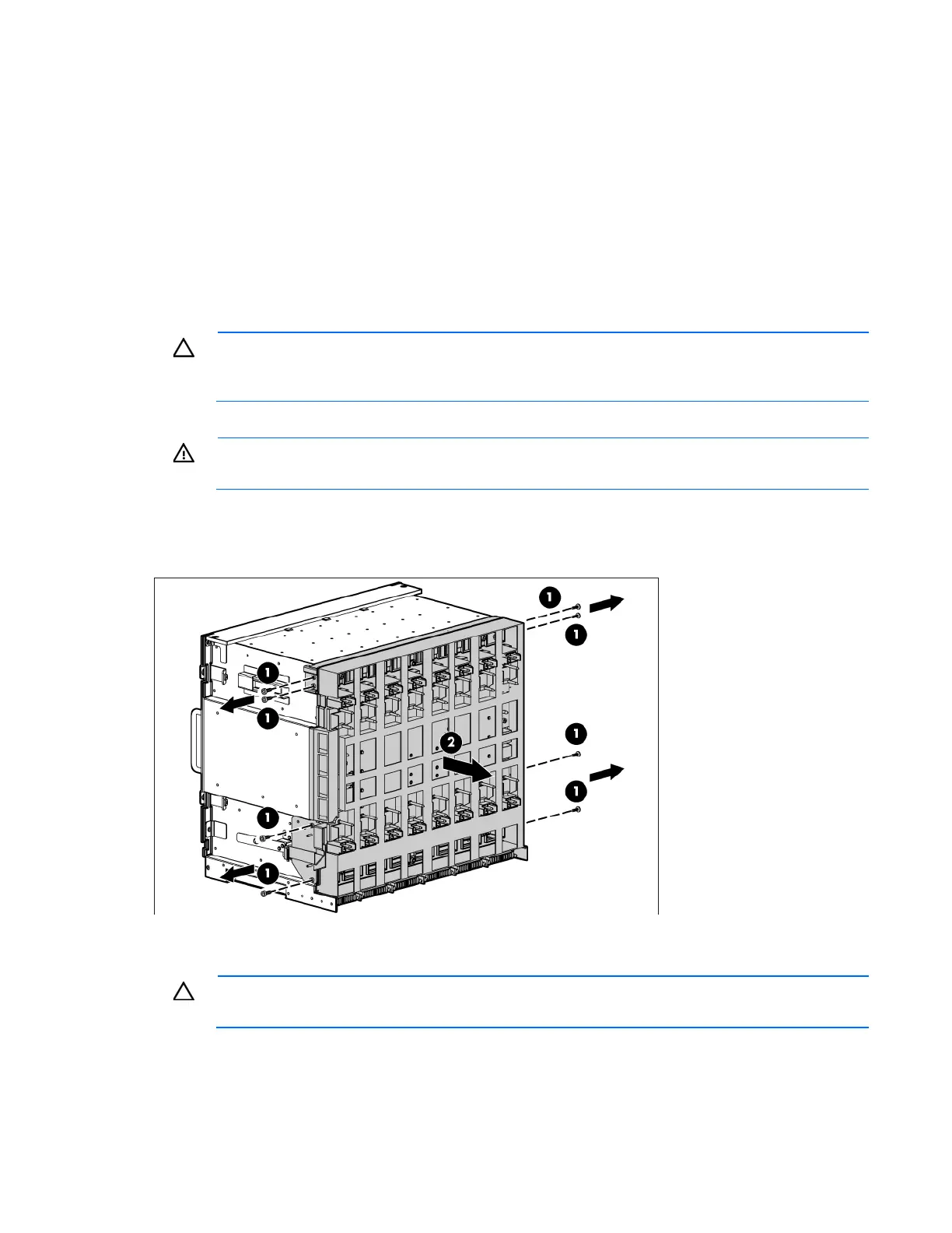
11. Remove the eight slotted T-15 Torx screws that secure the midplane assembly, and then remove the
midplane assembly from the rear cage.
To replace the midplane assembly, reverse the removal procedure. Place the new insulation bands around
the midplane assembly as available in the new midplane spare parts box.
CAUTION: The LCD cable must be correctly routed for proper operation.
Routing the LCD cable