Midplane assembly replacement 69
1.
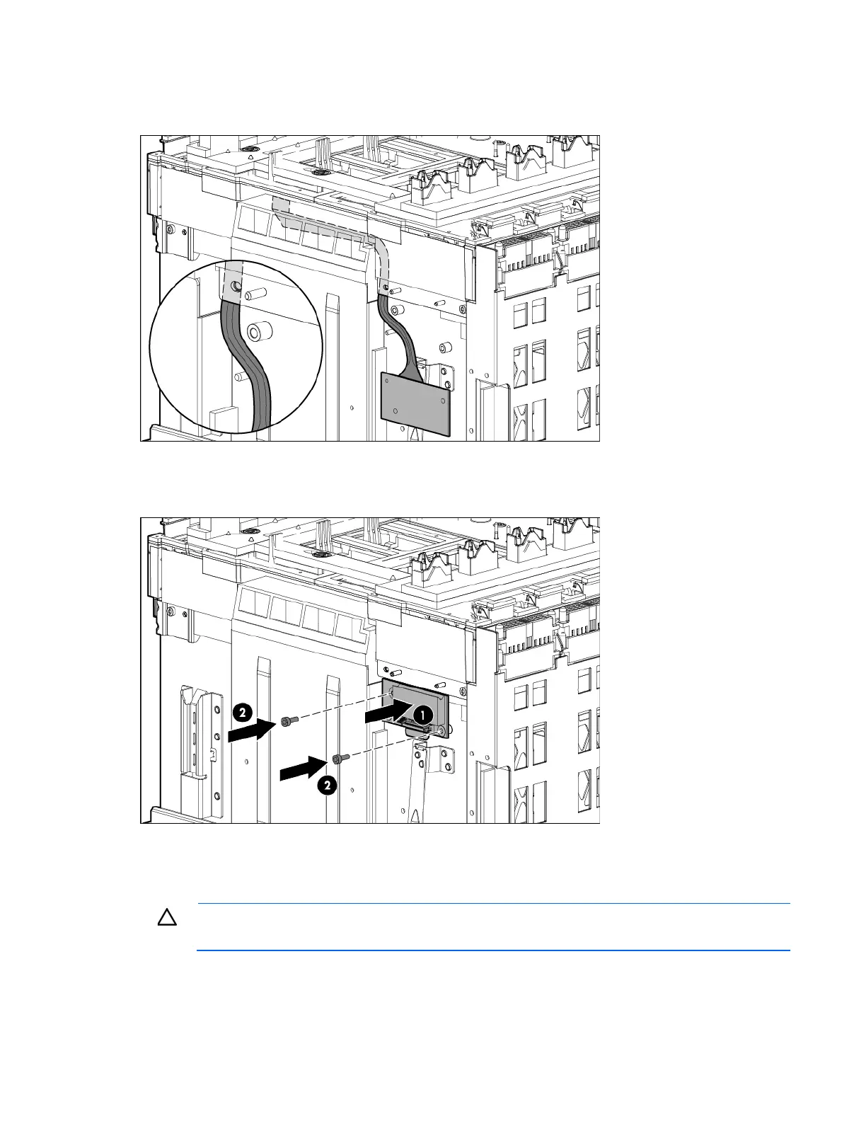
When installing the midplane assembly onto the rear cage assembly, ensure the LCD cable is routed
behind the interconnect module rubber boot and through the sheet-metal gaps. Route the cable as
shown in the following figure.
2. Route the cable between the Insight Display signal pass-thru board pin guide and the screw mounts. Be
careful not to pinch the cable between the Insight Display signal pass-thru board and the screw mount
as shown in the following figure.
3. Place the Insight Display signal pass-thru board properly over the guide pin and the screw mount and
screw the Insight Display signal pass-thru board to the rear cage assembly.
Verifying the enclosure serial number
CAUTION: Failure to complete the following procedure might cause inaccurate or incomplete
information to appear in HP SIM and Onboard Administrator.
1. Use the Insight Display to navigate to the Enclosure Info screen.
 Loading...


