65
Chapter 3: Connecting to a Target System
Designing the Target System for an Emulation Probe/Module
probe/module requires a debug port (BDM) connector in the target
system.
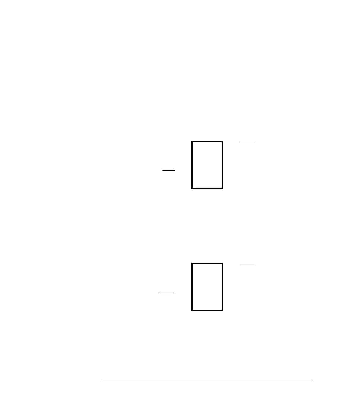
The connector should be a dual row header strip (“Berg connector”),
10 pins per inch, with 25 mil pins.
There are three possible pin outs of the BDM connector for the
MPC555. While these can be picked based on the application, there are
preferred pin outs for specific applications.
MPC505/509 Debug Port Connector
Pins 1 and 6 may be connected to VFLS0 and VFLS1 respectively, or, if
a single freeze line is used, to the FRZ line.
MPC555 Debug Port Connector, Option 1
For maximum debug capability (access to BDM and program trace
signals):
The E3497-66502 target interface module (TIM) requires 10k ohm
pull-up resistors on pins 1 and 6.
The E3497-66503 target interface module (TIM) has 10k ohm pull-up
resistors on pins 1 and 6.
9)/6)5=
■■
65(6(7
*1'
■■
'6&.
*1'
■■
9)/6)5=
5(6(7
■■
'6',
9RG
■■
'6'2
9)/6B03,2%
■■
65(6(7
*1'
■■
7&.B'6&.
*1'
■■
9)/6B03*,2%
+5(6(7
■■
7',B'6',
9RG
■■
7'2B'6'2