Communication 76
Pin number Signal name Function Direction from the UPS
4
— No connection —
5
GND Signal common (tied to chassis) —
6
— No connection —
7
— No connection —
8
— No connection —
9
— No connection —
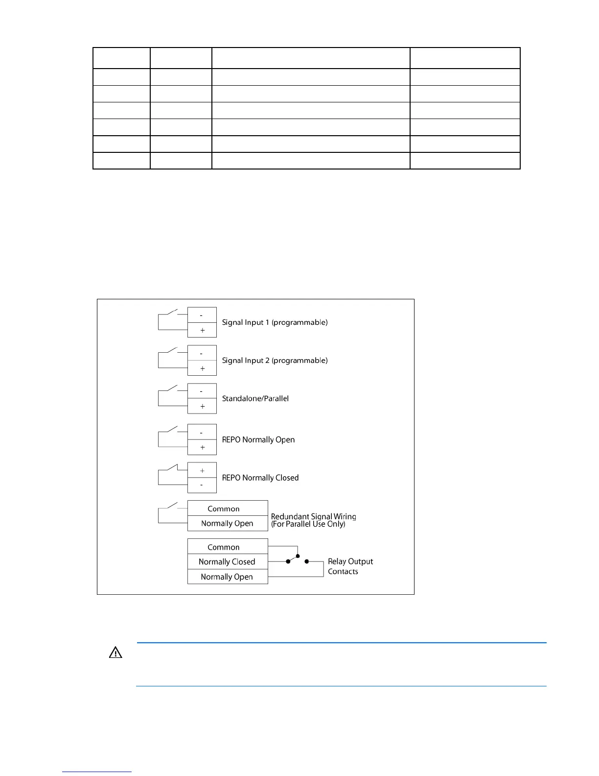
Control terminals
The cables should be connected to the control terminal with a mating connector. Input and output terminals
have a functional isolation from terminal to terminal. They are connected to the UPS chassis through
individual 1 MW resistors.
If using a semiconductor switch type, pay attention to the proper polarity. A relay or other mechanical control
is preferred.
Relay output contacts
WARNING: The relay output contacts must not be connected to any utility connected circuits.
Reinforced insulation to the utility is required. The relay output contacts have a maximum rating of
30 VAC/1 A and 60 Vdc/2 A nominal values.

 Loading...