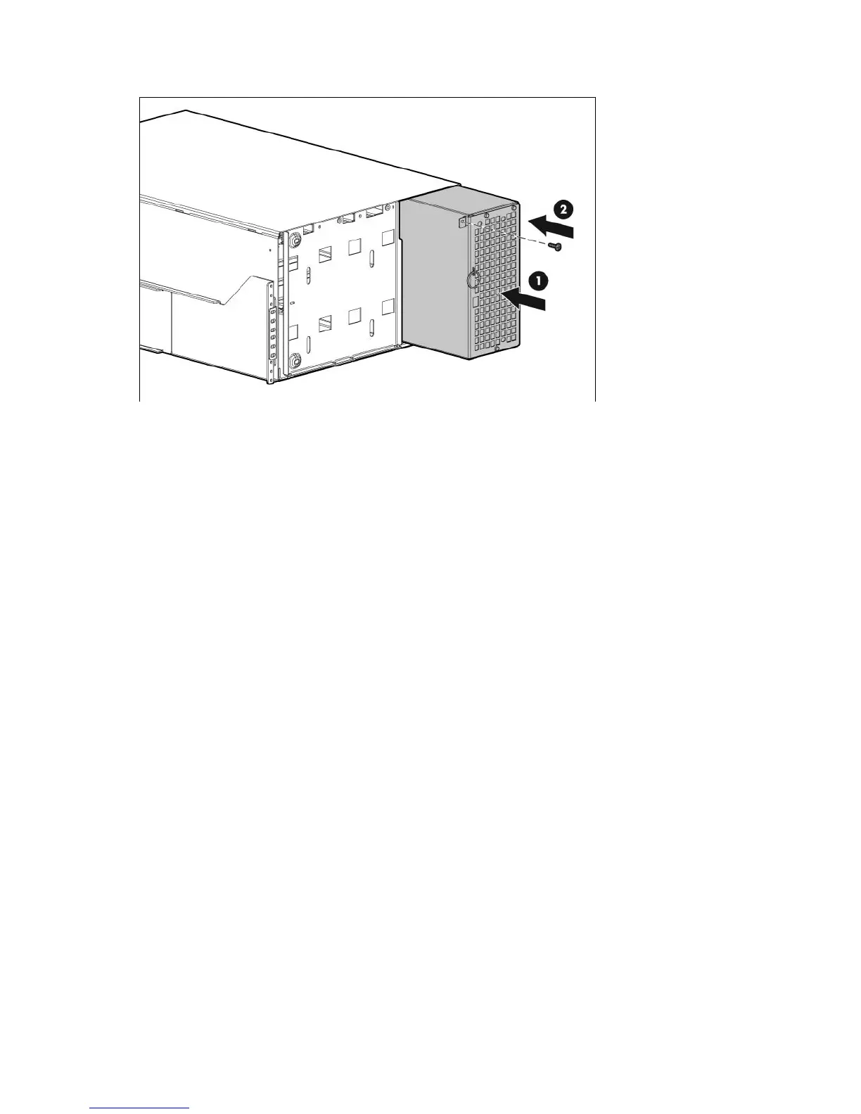
EasyManuals Logo

HP R1500 - UPS XR User Manual

HP R1500 - UPS XR
115 pages
To Next Page IconTo Next Page
To Previous Page IconTo Previous Page
Page #83 background imageLoading...
Page #83 background image
Maintenance 83
7.
Replace the screw.
8. If the configuration is parallel, reconnect the redundant signal cables.
9. Replace the front bezel.
10. Transfer the UPS to Normal mode (on page 65).
Replacing UPS X-Slot cards
This component is hot-swappable and can be replaced without powering down the UPS.
1. (optional) To replace the component with the UPS powered down, do one of the following:
o Standalone UPS configuration—See "Powering down the standalone UPS (on page 72)."
o Individual UPS in a parallel configurationSee "Powering down an individual paralleled UPS (on
page 72)."
o Parallel UPS configurationSee "Powering down the parallel system (on page 73)."
2. Disconnect the communications cable from the X-Slot Card.

Table of Contents

Questions and Answers:

Question and Answer IconNeed help?

Do you have a question about the HP R1500 - UPS XR and is the answer not in the manual?

HP R1500 - UPS XR Specifications

General IconGeneral
TopologyLine Interactive
Input ConnectionIEC 320 C14
Battery TypeSealed Lead Acid (SLA)
Form FactorRackmount
Nominal Output Voltage230V
Nominal Input Voltage230V
Input Frequency50/60 Hz
Typical Backup Time at Full Load5 minutes
Transfer Time4-8 ms
Hold-up Time10 ms
Input Voltage Range160 - 286 VAC
Interface PortUSB
Battery Recharge Time3 hours
Communication PortsUSB
WaveformSine wave

Related product manuals