EasyManuals Logo

HP R1500 - UPS XR User Manual

HP R1500 - UPS XR
115 pages
To Next Page IconTo Next Page
To Previous Page IconTo Previous Page
Page #84 background imageLoading...
Page #84 background image
Maintenance 84
3.
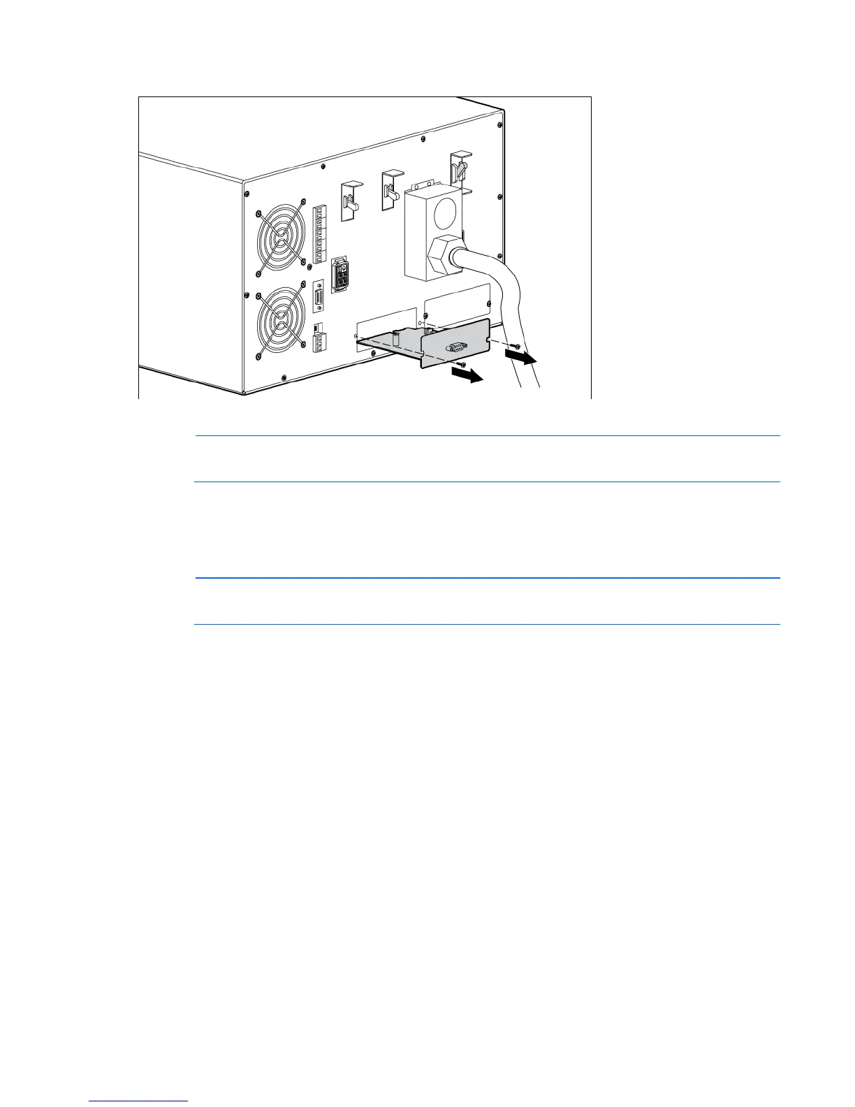
Remove the two screws securing the X-Slot Card and slide the card out.
To replace the component, reverse the removal procedure.
NOTE: Replacing the HP Management Module might require power management software to be
restarted or reconfigured.
Configuring the Parallel UPS Card
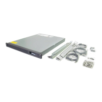
1. Unpack the Parallel UPS Card, and be sure that the card was not damaged during shipment.
NOTE: If installing another X-Slot card, be sure to install the Parallel UPS Card in X-Slot
Communication Bay 2.
2. Remove the UPS X-Slot communication bay cover, and retain the screws.
3. Set the jumper pins on the Parallel UPS Card according to the parallel configuration.
For three or more paralleled UPSs:
o Set the cards of the first and last UPS to Pins 1 and 2.

Table of Contents

Questions and Answers:

Question and Answer IconNeed help?

Do you have a question about the HP R1500 - UPS XR and is the answer not in the manual?

HP R1500 - UPS XR Specifications

General IconGeneral
TopologyLine Interactive
Input ConnectionIEC 320 C14
Battery TypeSealed Lead Acid (SLA)
Form FactorRackmount
Nominal Output Voltage230V
Nominal Input Voltage230V
Input Frequency50/60 Hz
Typical Backup Time at Full Load5 minutes
Transfer Time4-8 ms
Hold-up Time10 ms
Input Voltage Range160 - 286 VAC
Interface PortUSB
Battery Recharge Time3 hours
Communication PortsUSB
WaveformSine wave

Related product manuals