78 REMOVAL AND REPLACEMENT PROCEDURES
Install the first matched DIMM pair in socket set A.
Install subsequent matched DIMM pairs in sets B, then C, and lastly D (farthest from power supply).
The BIOS generates warnings/errors on invalid memory configurations.
In DDR2 mode, dual-rank DIMMs are placed farther from the Memory Controller Hub (MCH) than
single-rank DIMMs.
If there is no way to obtain a valid memory configuration by disabling some of the plugged-in memory,
the BIOS will halt with a diagnostics 2004 code for memory error (4 beeps/blinks).
If the BIOS can find a valid memory configuration by disabling some of the plugged-in memory, it will
do so and will report a warning during POST (“215-mismatched memory”). The system can still be
booted in this condition.
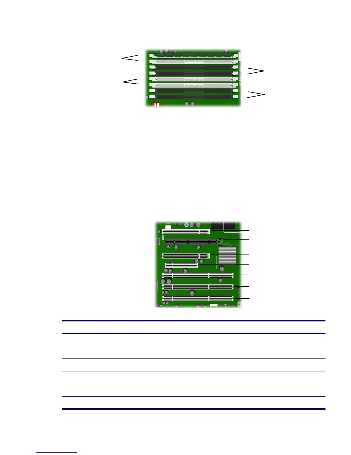
Peripheral Component Interconnect (PCI) Slots
Table 4-4 PCI Slot Types
Slot Type Ref
1PCI J21
2 PCI Express x16 J41
3PCI J20
4 PCI Express x4 J31
5 PCI-X 133 J22
6 PCI-X 100 J23
1
2
A
5
6
C
3
4
B
7
D
8
SIDE CLOSEST TO PCI SLOTS
1
2
3
4
5
6
7
 Loading...