REMOVAL AND REPLACEMENT OF COMPONENTS 89
Chapter 4
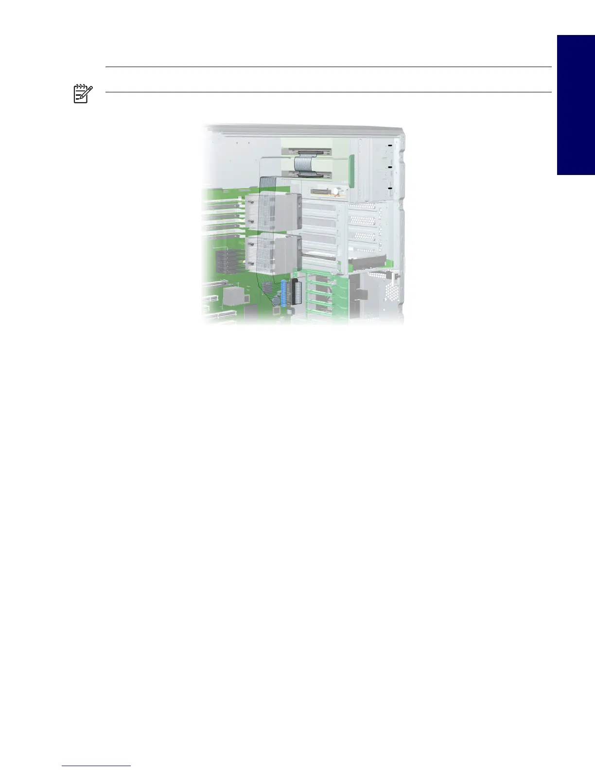
If you are installing more than one optical drive, route the cable as in the following image.
NOTE The optical drive cable is routed under the system board.
Replacing Optical Drive Cable
The optical IDE cable is routed behind the system board.
1 Disconnect power from the system (page 66), remove the access panel (page 71), lay the
workstation on its side with the system board facing up, remove all expansion boards and graphics
cards (page 84), remove the CPU heatsinks (page 96), disconnect the optical IDE cable from the
system board, and remove the system board (page 101).
2 Remove the plastic ties and tape from the IDE cable, then remove the IDE cable
3 Replace the cable and cable ties. Refer to the previous image for cable routing information.
Diskette Drive (Optional)
To remove a diskette drive:
1 Disconnect power from the system (page 66), remove the access panel (page 71), and remove the
front bezel (page 71).
 Loading...