203
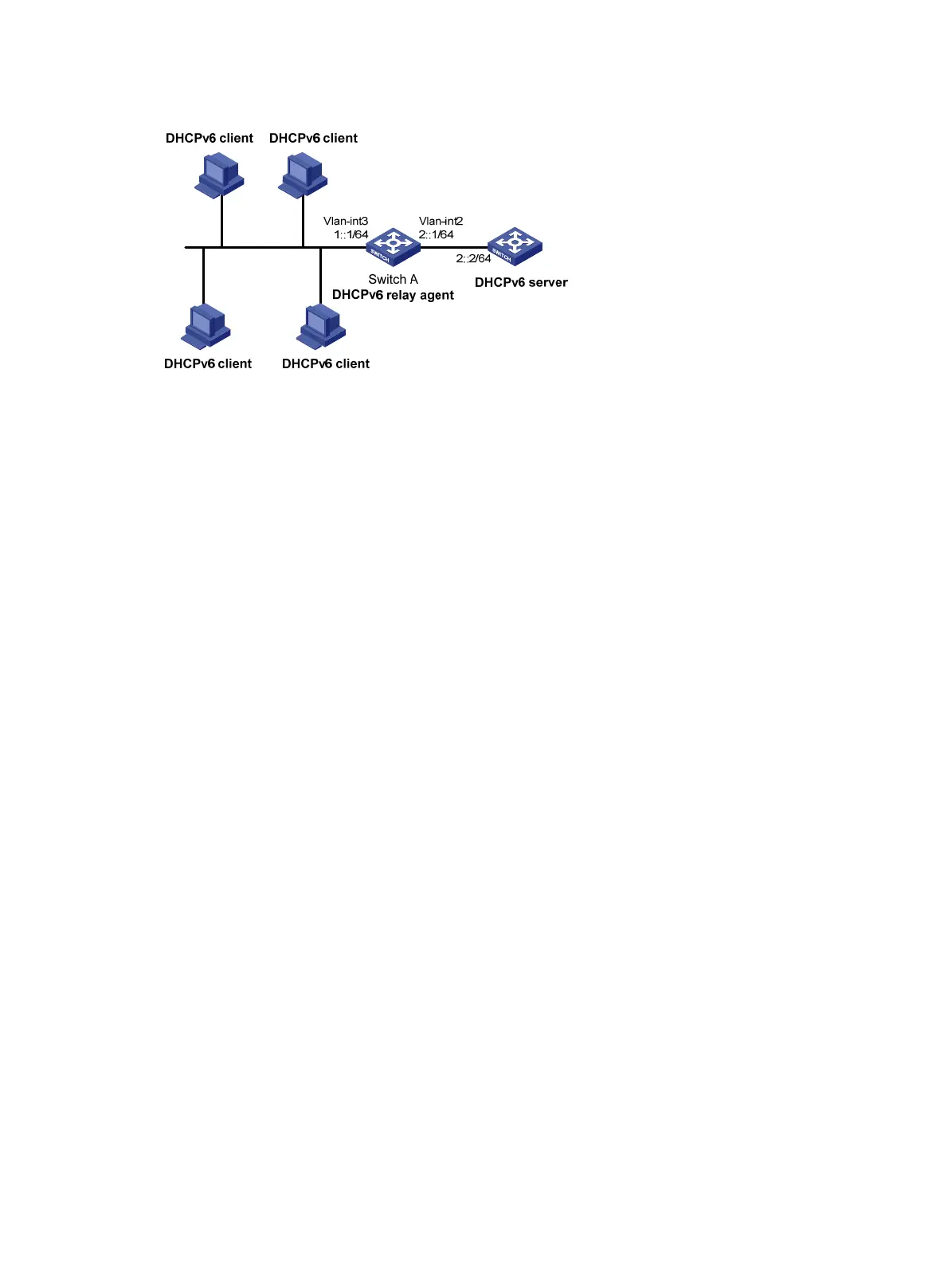
Figure 76 Network diagram
Procedure
# Specify IPv6 addresses for VLAN-interface 2 and VLAN-interface 3.
<SwitchA> system-view
[SwitchA] interface vlan-interface 2
[SwitchA-Vlan-interface2] ipv6 address 2::1 64
[SwitchA-Vlan-interface2] quit
[SwitchA] interface vlan-interface 3
[SwitchA-Vlan-interface3] ipv6 address 1::1 64
# Disable RA message suppression on VLAN-interface 3.
[SwitchA-Vlan-interface3] undo ipv6 nd ra halt
# Set the M flag to 1 in RA advertisements to be sent on VLAN-interface 3. Hosts that receive the RA
advertisements will obtain IPv6 addresses through DHCPv6.
[SwitchA-Vlan-interface3] ipv6 nd autoconfig managed-address-flag
# Set the O flag to 1 in RA advertisements to be sent on VLAN-interface 3. Hosts that receive the RA
advertisements will obtain information other than IPv6 address through DHCPv6.
[SwitchA-Vlan-interface3] ipv6 nd autoconfig other-flag
# Enable the DHCPv6 relay agent on VLAN-interface 3 and specify the DHCPv6 server on the relay
agent.
[SwitchA-Vlan-interface3] ipv6 dhcp select relay
[SwitchA-Vlan-interface3] ipv6 dhcp relay server-address 2::2
Verifying the configuration
# Display DHCPv6 server address information on Switch A.
[SwitchA-Vlan-interface3] display ipv6 dhcp relay server-address
Interface: Vlan-interface3
Server address Outgoing Interface
2::2
# Display packet statistics on the DHCPv6 relay agent.
[SwitchA-Vlan-interface3] display ipv6 dhcp relay statistics
Packets dropped : 0
Packets received : 14
Solicit : 0
Request : 0
Confirm : 0

 Loading...


