76
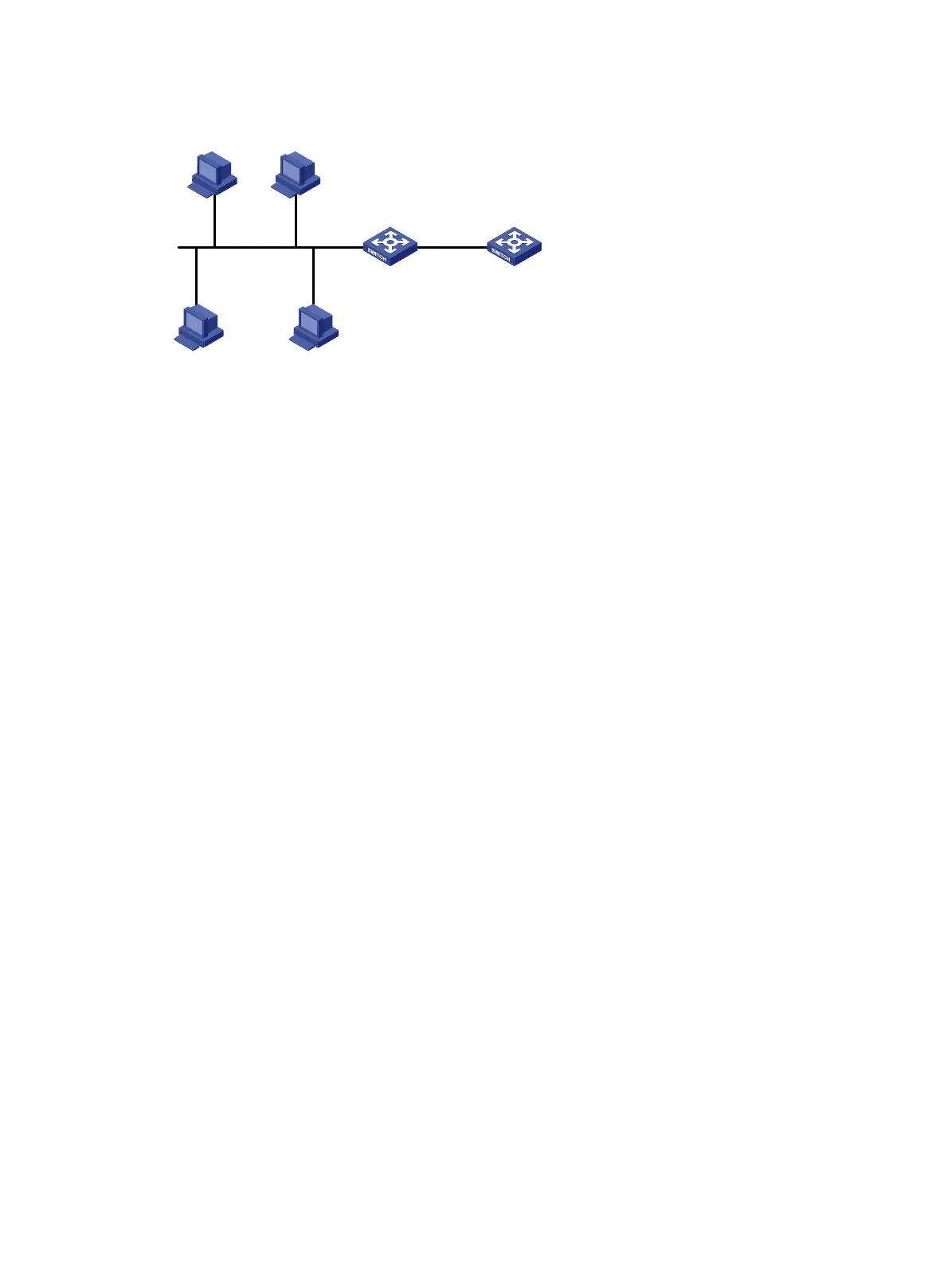
Figure 25 Network diagram
Procedure
# Specify IP addresses for the interfaces. (Details not shown.)
# Enable DHCP.
<SwitchA> system-view
[SwitchA] dhcp enable
# Enable the DHCP relay agent on VLAN-interface 10.
[SwitchA] interface vlan-interface 10
[SwitchA-Vlan-interface10] dhcp select relay
# Specify the IP address of the DHCP server on the relay agent.
[SwitchA-Vlan-interface10] dhcp relay server-address 10.1.1.1
Verifying the configuration
# Verify that DHCP clients can obtain IP addresses and all other network parameters from the DHCP
server through the DHCP relay agent. (Details not shown.)
# Display the statistics of DHCP packets forwarded by the DHCP relay agent.
[SwitchA] display dhcp relay statistics
# Display relay entries if you have enabled relay entry recording on the DHCP relay agent.
[SwitchA] display dhcp relay client-information
Example: Configuring Option 82
Network configuration
As shown in Figure 25, the DHCP relay agent (Switch A) replaces Option 82 in DHCP requests
before forwarding them to the DHCP server (Switch B).
• The Circuit ID sub-option is
company001.
• The Remote ID sub-option is
device001.
To use Option 82, you must also enable the DHCP server to handle Option 82.
Procedure
# Specify IP addresses for the interfaces. (Details not shown.)
# Enable DHCP.
<SwitchA> system-view
[SwitchA] dhcp enable
Switch B
DHCP server
Switch A
DHCP relay agent
DHCP client DHCP client
DHCP clientDHCP client
Vlan-int20
10.1.1.2/24
Vlan-int10
10.10.1.1/24
Vlan-int20
10.1.1.1/24

 Loading...