Chapter 6 Function Introduction Shenzhen Hpmont Technology Co., Ltd
―96― HD30 Series Inverters User Manual
No. Name Description Range
factory setting
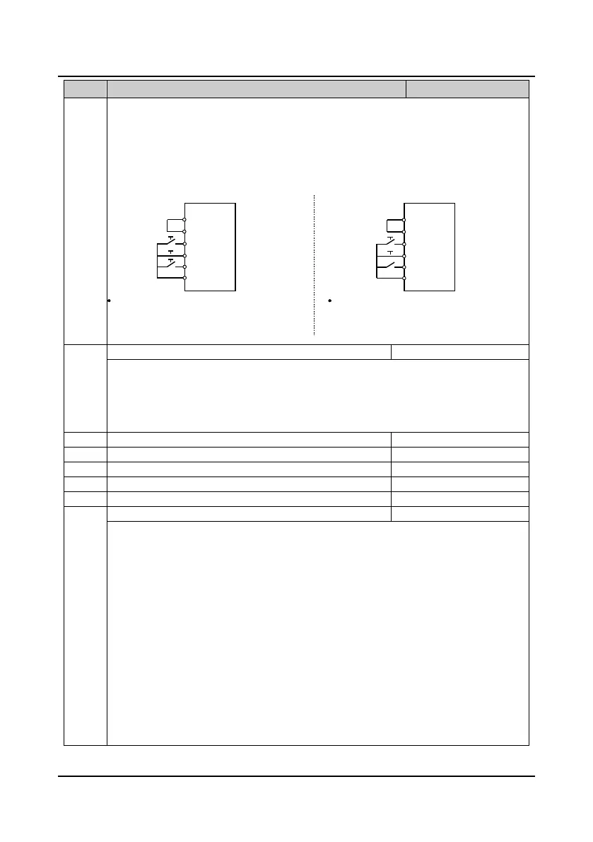
2: Three-wire operation mode 1.
• If the shift between SB2 and SB3 is disabled, the inverter will hold the control mode.
3: Three-wire operation mode 2.
• If SB2 changes from enabled into disabled, the inverter will keep the same mode.
• DIi can be selected by the multi-function input terminal DIi. At this time, the function of this terminal
should be defined as No. 4 function of “three-wire operation”.
F15.17 Terminal operating selection due to fault of external equipment 0
3
0
When there is fault of external equipment, it can select protection.
0: Coast to stop.
1: Emergency stop.
2: Decelerate to stop.
3: Continue to run.
DO1 terminal function selection
F15.19 DO2 terminal function selection 0
38
0
RLY1 relay function selection
F15.21 RLY2 relay (extension relay) function selection 0
35
0
RLY3 relay (extension relay) function selection
F15.23 RLY4 relay (extension relay) function selection 0
35
0
0: Reserved. There is no output function and action of the output terminal.
1: Inverter ready. The inverter completes power on and no fault occurs, then it can normally run the
indicating signal.
2: Inverter is running. The inverter is in run status and output indicatiing signal.
3: Inverter is forward running. The inverter is forward running the indicating signal.
4: Inverter is reverse running. The inverter is reverse running the indicating signal.
5: Inverter is DC braking. The inverter is DC braking the indicating signal.
6: Inverter is in zero-frequency status. In the zero-frequency range the inverter’s output frequency
(including in stop status) outputs the indication signal.
• Refer to parameters F15.28 and F15.29.
7: Inverter is in zero-frequency running. In the zero-frequency range the inverter’s output frequency
outputs the indicating signal.
• Refer to parameters F15.28 and F15.29.
8: Reserved.
9,10: Frequency detection threshold (FDT1,FDT2).
• Refer to parameters F15.31-F15.35.
SB1
SB2
SB3
K
SB1
SB2
Three-wire operation mode 1
SB1:Normally-closed stop button (effective at the falling edge)
SB2:Normally-open forward button (effective at the risling edge)
SB3:Normally-open reverse button (effective at the rising edge)
K:Direction selection button (level on)
COM
REV
DIi
FWD
SEL
P24
COM
REV
DIi
FWD
SEL
P24
SB1:Normally-closed stop button (effective at the falling edge)
SB2:Normally-open run button (effective at the risling edge)
K = 0 (forward) K = 1 (reverse)
Three-wire operation mode 2
 Loading...


