Shenzhen Hpmont Technology Co., Ltd Chapter 6 Function Introduction
HD30 Series Inverters User Manual ―95―
No. Name Description Range
factory setting
F15.12 Acceleration/deceleration rate of UP/DN terminal 0.00
99.99
1.00 Hz/s
It defines the change rate of setting frequency via the UP/DN terminal.
F15.13 Terminal detecting interval 0
2
0
0: 2ms
1: 4ms
2: 8ms
F15.14 Terminal detecting filter number 0
10000
2
The digital input terminal signal should be delayed and confirmed so as to avoid digital input error.
F15.15 Terminal input positive and negative logic setting 000
0x1FF
000
It defines that each bit (binary) of this function represents different physical sources.
• Positive logic: When multi-function input terminals are connected to corresponding common port,
this logic is enabled. Otherwise the logic is disabled.
• Negative logic: When multi-function input terminals are connected to corresponding common port,
this logic is disabled. Otherwise the logic is enabled.
Hundreds Tens Units
Bit11 Bit10 Bit9 Bit8 Bit7 Bit6 Bit5 Bit4 Bit3 Bit2 Bit1 Bit0
- - - DI9 DI8 DI7 DI6 DI5 DI4 DI3 DI2 DI1
• 0 means positive logic while 1 means negative logic.
Note: Only when using HD30-EIO will DI7
DI9 be enabled.
F15.16 FWD/REV operation mode 0
3
0
• FWD can be selected by multi-function input terminal DIx and represented as “FWD”. At this time,
the function of this terminal should be defined as No. 2 function.
• REV can be selected by multi-function input terminal DIy and represented as “REV”. At this time,
the function of this terminal should be defined as No. 3 function.
This function defines the four control modes via the external terminals.
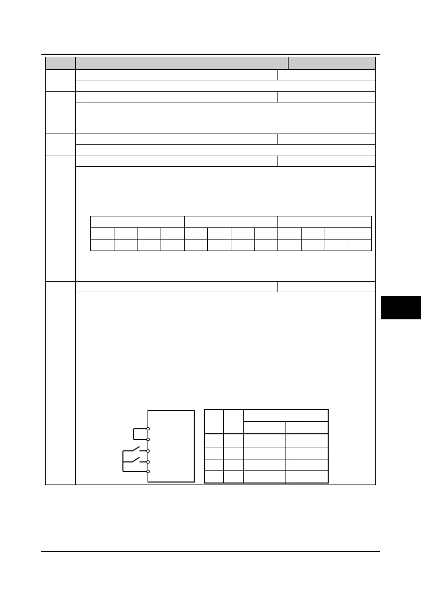
0: Two-wire operation mode 1.
1: Two-wire operation mode 2.
• When stop command coming from other sources makes the inverter stopping though the
terminal logic enabled in the terminal control mode, there is no run command even the control
terminal FWD/REV are still valid.
• If you want the inverter to run again, you should trigger the active FWD and REV. For example:
The terminal function set as 12, 41-45 or PLC stop after single cycle.
P24
SEL
FWD
REV
COM
K1
K2
K1K2
00
01
11
10
Mode 2Mode 1
Run command
Stop
Stop
Stop
Stop
Forward
Reverse
Forward
Reverse
6
 Loading...


