Shenzhen Hpmont Technology Co., Ltd. Chapter 4 Electrical Installation
HD3N Series User Manual V1.1 - 29 -
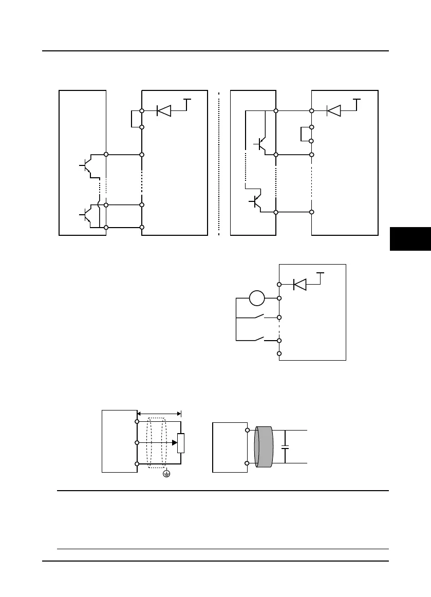
Using internal 24V power supply of HD3N, it is NPN / PNP connection in which external controller is
common emitter output, as shown in Figure 4-8. (For PNP, remove the connector between SEL and
P24)
Figure 4-8 Connection when using internal 24V power supply
AC signal
DI terminal can input AC signal, refer to
Figure 4-9. (Remove the connector
between SEL and P24)
Figure 4-9 Connection when AC signal inputs (7.5 - 75kW)
Analogue Input (AI) Connection
The AI1 is voltage input and the range is 0 - 10V, as shown in Figure 4-10.
Figure 4-10 AI1 connection
Note:
1. To reduce the interference and attenuation of control signal, length of control cable should limit within
50m, and the shield should be reliably grounded.
2. In serious interference occasions, the analogue input signal should add filter capacitor and ferrite core, as
shown in Figure 4-10.
External controller
+24V
P24
SEL
DI1
COM
DI6
6
1
NPN
Using internal
power supply
External controller
+24V
P24
SEL
DI1
COM
DI6
6
1
PNP
Using internal
power supply
+ 24V
COM
P24
SEL
K6
K1
12-30V
AC
AC
DI1
DI6
AI1
GND
GND
AI1
+10
PE
Potentiometer
Signal linewinding ontheferritecore
for 2or 3turns.
Filter capacitor
0.022uF/50V
Ferrite core
< 50m

 Loading...

