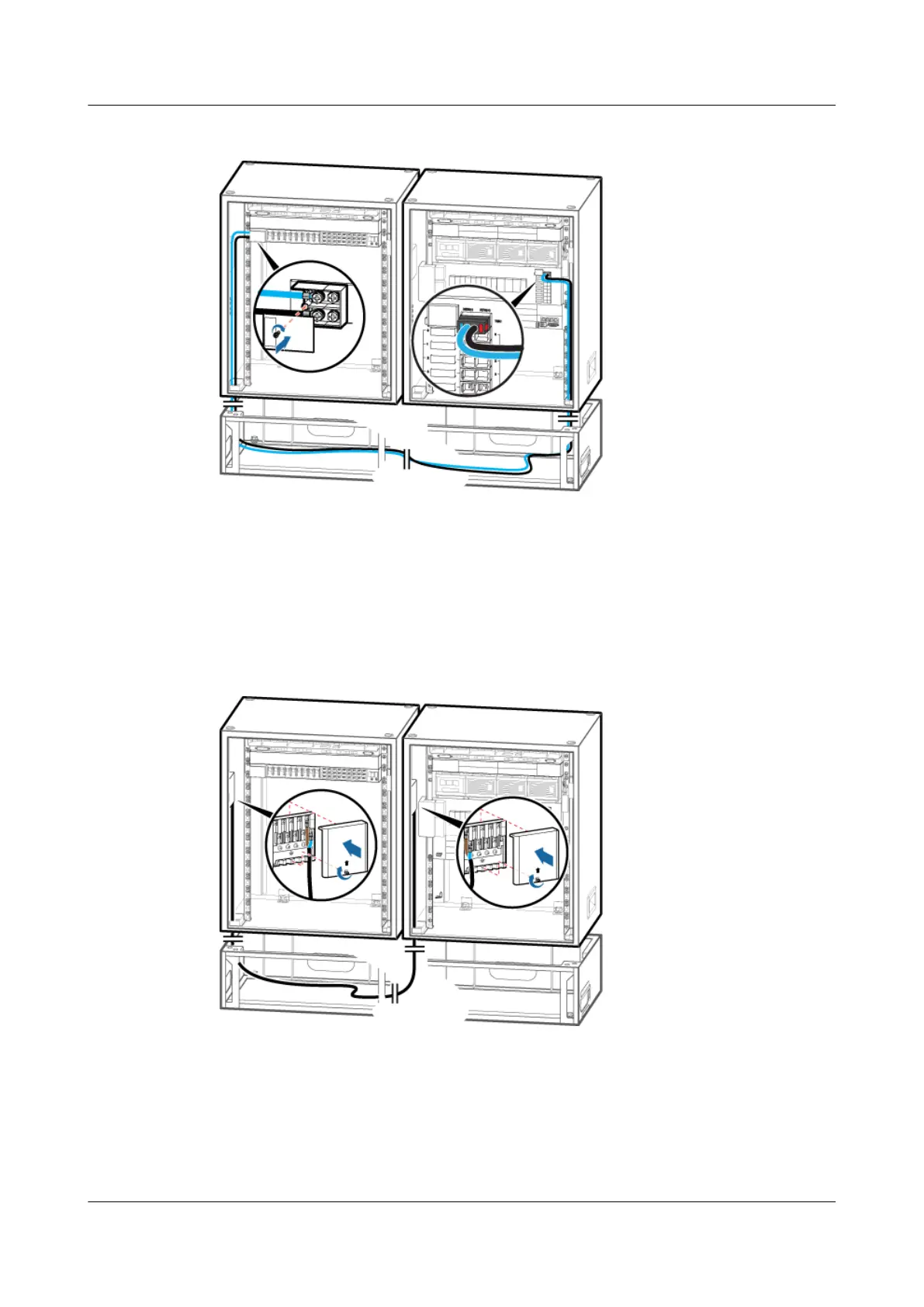
Figure 12-10 Installing the input power cable for the TMC11H
Step 3 Link the OT terminal at one end of the power cable for the junction box in the TMC11H to the
AC output wiring terminals labeled L3 and N3 in the junction box in the APM30H, and then
link the OT terminal at the other end to the AC input wiring terminal labeled L and N in the
junction box in the TMC11H, as shown in Figure 12-11.
Figure 12-11 Installing the power cable for the junction box in the TMC11H
Step 4 Route the cable by referring to 12.1 Cabling Requirements, and then use cable ties to bind the
cable.
Step 5 Attach labels to the installed cable. For details, see Attaching a Sign Plate Label.
BTS3900A(Ver.B)
Installation Guide 12 Installing the Cables
Issue 01 (2011-10-25) Huawei Proprietary and Confidential
Copyright © Huawei Technologies Co., Ltd.
93