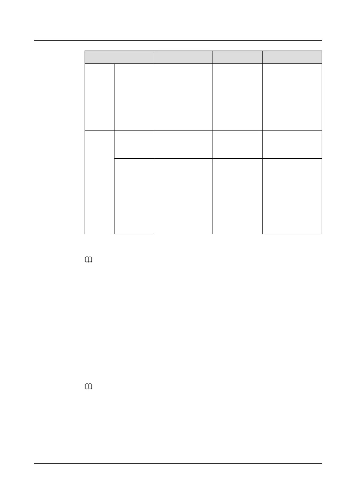
Cable One End The Other End Remarks
from the
RFC)
NEG(-) wire OT terminal (2.5
mm
2
, M6)
Blue
Input
power
cable for
the
TMC11
H
(supplie
d with
power
from the
external
equipme
nt)
RTN(+) wire
OT terminal (4
mm
2
, M6)
According to the
external
equipment
Black
NEG(-) wire OT terminal (4
mm
2
, M6)
According to the
external
equipment
Blue
NOTE
In the -48 V DC power supply scenario, the RFC can obtain the power only from the external equipment. The
TMC11H, however, can obtain power from the external power equipment or from the RFC. If the TMC11H
obtains power from the RFC, the total power consumption of the TMC11H cannot exceed 800 W.
Procedure
Step 1 Prepare the input power cables for the RFC and TMC11H.
1. Prepare the cable of proper length based on the actual cable route.
2. Add connectors to both ends of the input power cable for the RFC and power cable for the
TMC11H according to Table 12-5. For details, see Assembling the OT Terminal and the
Power Cable.
Step 2 Link the OT terminal at one end of the input power cable for the RFC to the input wiring terminal
on the DCDU-01, tighten the screw, and then connect the other end to the external equipment,
as shown in Figure 12-22.
NOTE
Before installing the power cables, remove the protecting hood from the DC input wiring terminal block
on the DCDU-01. After the cables are installed, reinstall the protecting hood.
BTS3900A(Ver.B)
Installation Guide 12 Installing the Cables
Issue 01 (2011-10-25) Huawei Proprietary and Confidential
Copyright © Huawei Technologies Co., Ltd.
108