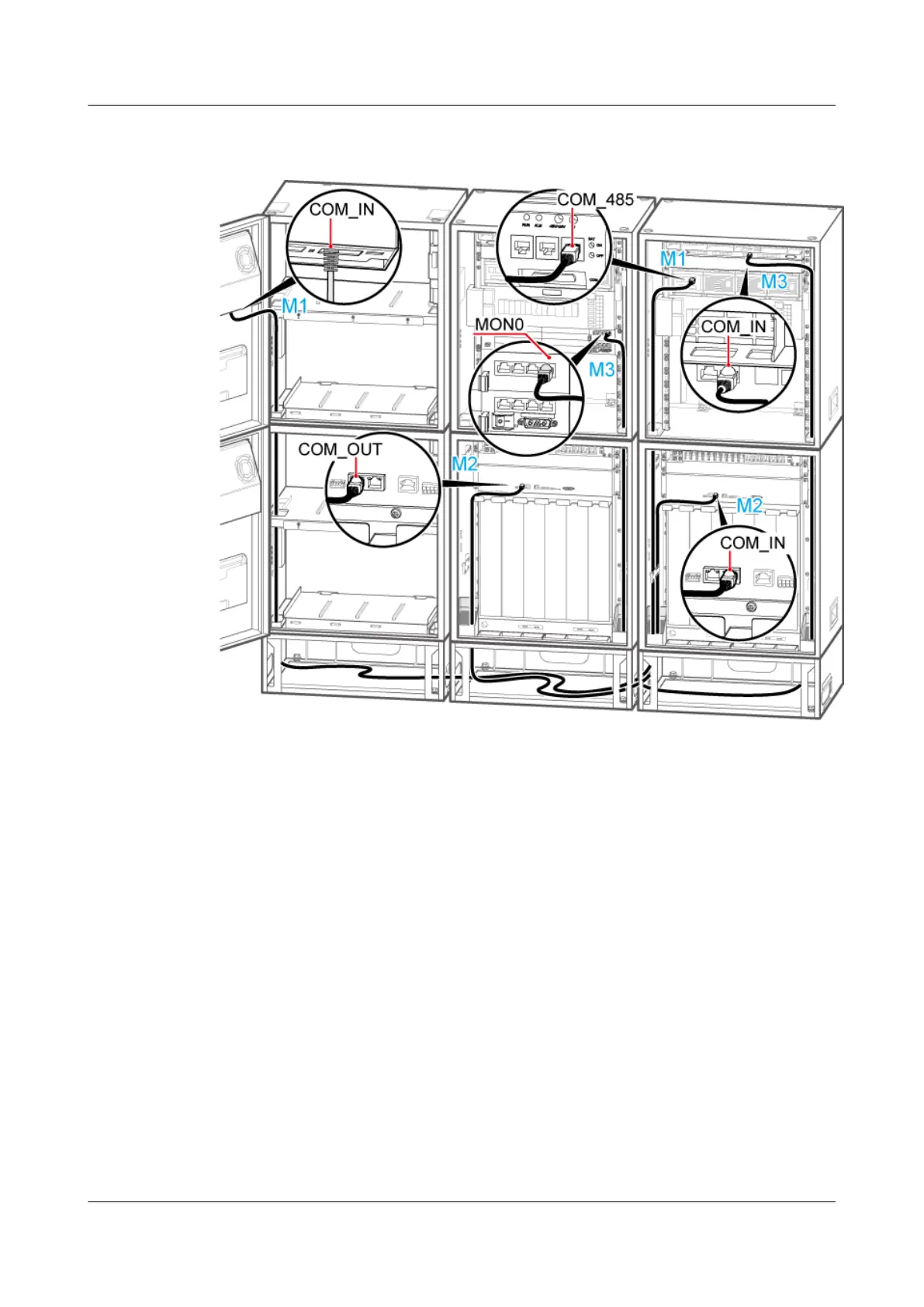
Figure 12-35 Installing the monitoring signal cable in the scenario of 2 RFCs+2 APM30Hs+2
IBBS200Ds/IBBS200Ts
2. Install the monitoring signal cable between the RFC and the extension RFC. Connect one
end of the cable to the COM_OUT port on the CMUA in the fan box of the RFC and the
other end to the COM_IN port on the CMUA in the fan box of the extension RFC, as shown
in Figure 12-33.
3. Install the monitoring signal cable between the CMUA and the BBU between the APM30H
and the extension APM30H. Connect one end of the cable to the MON0 port on the UEIU
in the BBU in the APM30H and the other end to the COM_IN port on the CMUA on the
cabinet door of the extension APM30H, as shown in Figure 12-35.
4. Attach labels to the installed cables. For details, see Attaching an L-Shaped Label.
5. Run each cable that leave the cabinet in a PVC corrugated pipe, and then tie the pipe to the
cable hole in the cabinet.
----End
Scenario: 1 RFC+1 APM30H+1 TMC11H
If a site is configured with one RFC, one APM30H, and one TMC11H, one monitoring signal
cable between the TMC11H and the RFC is required on site.
BTS3900A(Ver.B)
Installation Guide 12 Installing the Cables
Issue 01 (2011-10-25) Huawei Proprietary and Confidential
Copyright © Huawei Technologies Co., Ltd.
120