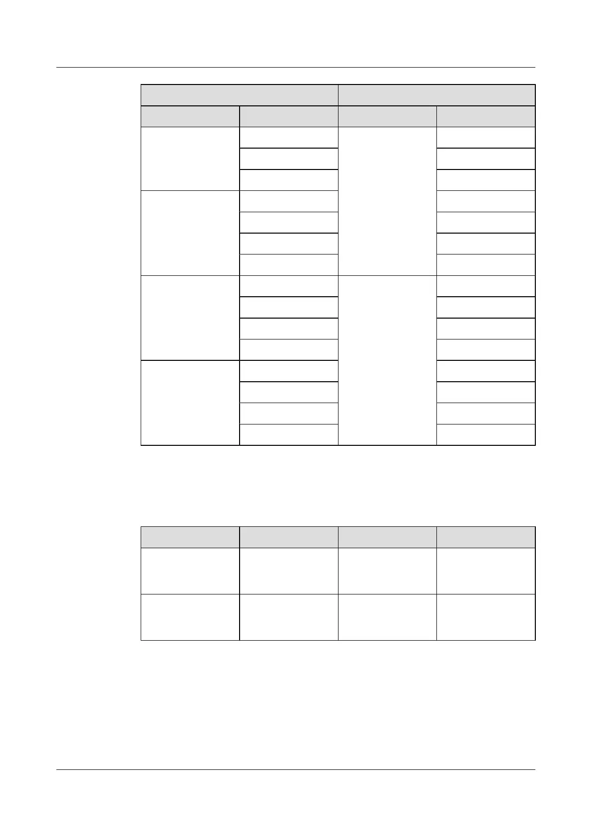
Input Output
Label Pin Label Pin
IN0.2 OUT1.2
IN0.3 OUT1.4
IN0.4 OUT1.5
IN1 IN1.1 OUT1.3
IN1.2 OUT1.6
IN1.3 OUT1.7
IN1.4 OUT1.8
IN2 IN2.1 OUT0 OUT0.1
IN2.2 OUT0.2
IN2.3 OUT0.4
IN2.4 OUT0.5
IN3 IN3.1 OUT0.3
IN3.2 OUT0.6
IN3.3 OUT0.7
IN3.4 OUT0.8
Table 11-2 lists the SLPU-related cables.
Table 11-2 SLPU-related cables
Cable
One End The Other End Remarks
Surge protection
transfer cable for
monitoring signals
RJ45 connector RJ45 connector Grey shielded
straight-through
cable
External dry-contact
monitoring signal
cable
Bare wire Depending on the
external equipment
-
Procedure
Step 1 Install cable racks on both sides of the SLPU and ensure that the mounting ears are on the same
plane as the SLPU panel, as shown in Figure 11-3.
BTS3900A(Ver.B)
Installation Guide 11 Installing Optional Modules
Issue 01 (2011-10-25) Huawei Proprietary and Confidential
Copyright © Huawei Technologies Co., Ltd.
59