Figure 12-1 Cable outlet modules in the RFC
NOTE
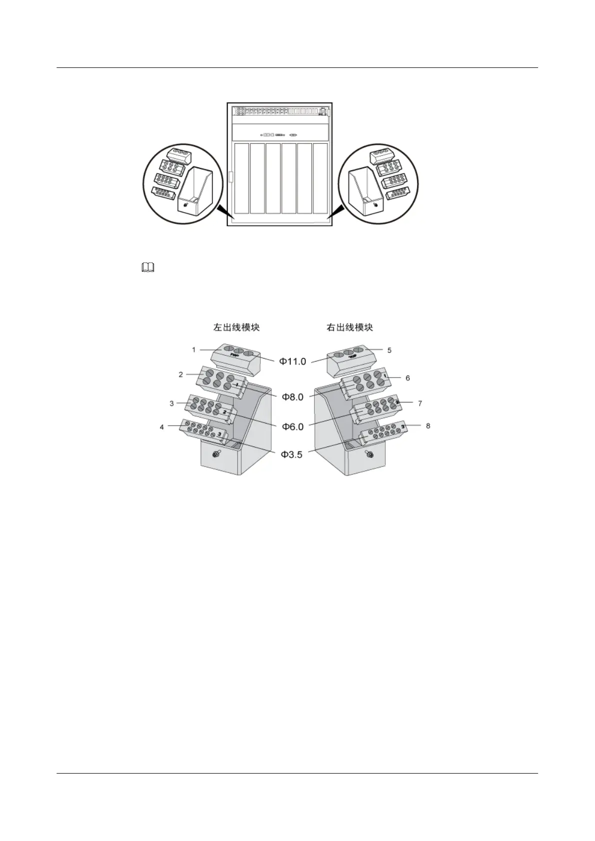
Figure 12-2 shows the exterior of the cable outlet modules of the RFC.
Figure 12-2 Exterior of the cable outlet modules of the RFC
(1) Cable holes for the AC input power cables and GPS
clock signal cables
(5) Cable hole for Boolean alarm signal cables
(2) Cable hole for the microwave IF cable and diesel
generator monitoring cable
(6) Cable hole for E1/T1 cables and storage battery
power cables
(3) AC output power cables, PGND cables, and DC
input power cables
(7) Cable hole for RS485 signal cables
(4) Cable holes for CPRI cables and Bias-Tee feeders (8) Cable holes for CPRI cables, Bias-Tee feeders,
and DC output power cables (of the TMC and
IBBS's FAN/TEC)
Cable module of TMC11H
There is a cable outlet module at both left and right sides of each TMC11H cabinet or IBBS200D/
IBS200T, as shown in Figure 12-3.
BTS3900A(Ver.B)
Installation Guide 12 Installing the Cables
Issue 01 (2011-10-25) Huawei Proprietary and Confidential
Copyright © Huawei Technologies Co., Ltd.
84