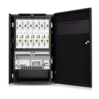
Table 13-1 describes the power switches on the DCDU-11A.
Table 13-1 Power switches on the DCDU-11A
Power switches on the DCDU-11A Module
LOAD0 RFU in slot 0
LOAD1 RFU in slot 1
LOAD2 RFU in slot 2
LOAD3 RFU in slot 3
LOAD4 RFU in slot 4
LOAD5 RFU in slot 5
LOAD6 FAN module
LOAD7 BBU
LOAD8 BBU
LOAD9 Reserved
NOTE
The numbers of the slots where the RFUs are installed are 0 to 5 from left to right.
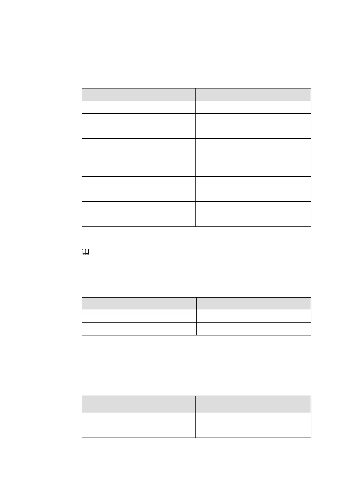
Table 13-2 lists the circuit breakers on the DCDU-11B panel.
Table 13-2 Circuit breakers on the DCDU-11B panel
Circuit Breaker on the DCDU-11B Panel Module
LOAD0 to LOAD5 RRUs
LOAD6 to LOAD9 Reserved
Procedure
Step 1 Turn on the switch of the external power supply to power on the BTS3900L.
Step 2 Check whether the input voltage of the DCDU in the BTS3900L is normal.
If Then
The input voltage of the DCDU is not in the
range from -38.4 V DC to -57 V DC
Power supply to the cabinet fails. Go to Step
3.
BTS3900L (Ver.C)
Installation Guide 13 Powering On the BTS3900L
Issue 07 (2013-11-08) Huawei Proprietary and Confidential
Copyright © Huawei Technologies Co., Ltd.
108
 Loading...