NetCol5000-A(025, 035) In-row Air Cooled Smart
Cooling Product
User Manual (600 mm)
Copyright © Huawei Technologies Co., Ltd.
The Arm7 main control board has the DIP switch, whereas the M4 does not have. If the
Arm7 main control board is used, set the DIP switch. If the M4 main control board is used,
skip this step because there is no DIP switch.
You need to set only the seventh toggle switch based on site requirements and leave the
rest of toggle switches in their default status listed in Table 3-16.
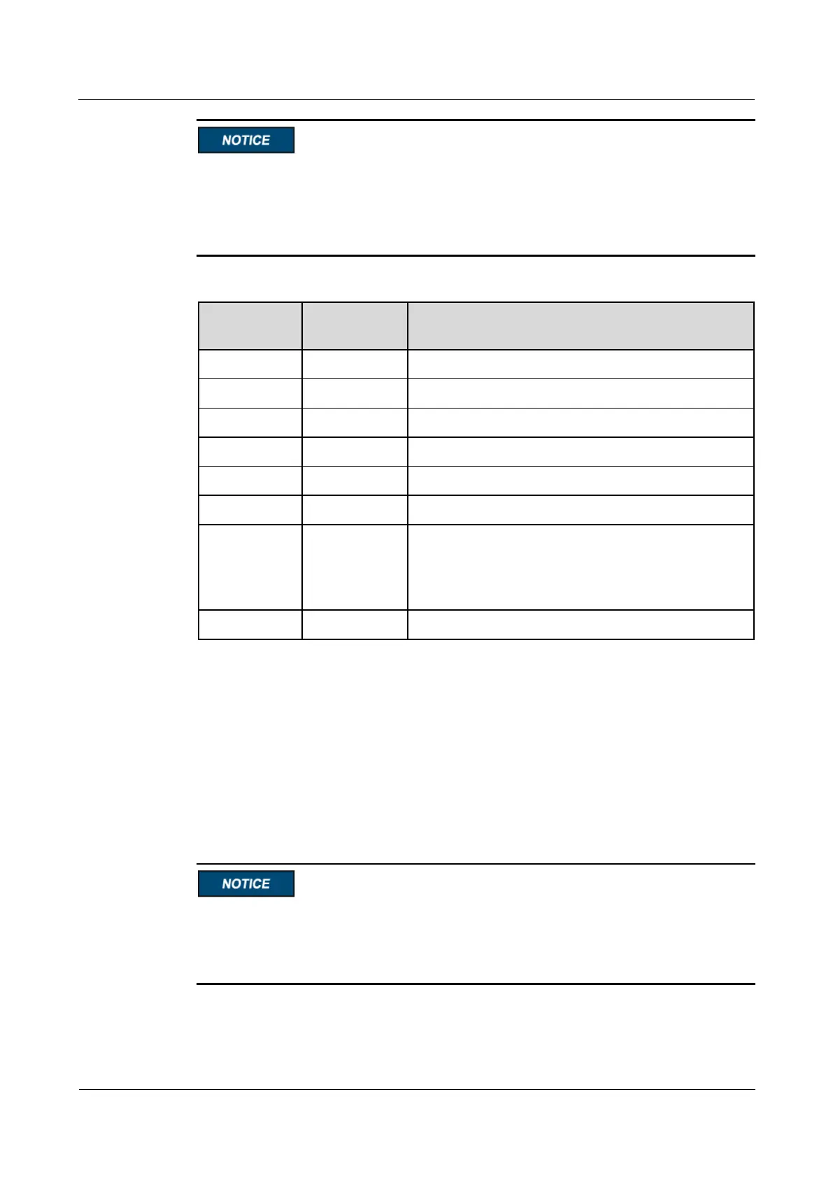
Table 3-16 Operation description of the toggle switches
Non-teamwork situations: remaining "OFF".
For teamwork situations, set toggle switch 7 of the
first and last smart cooling products to "ON" and
toggle switch 7 of other units to "OFF".
3.11.6 Installing a Humidity and Temperature Sensor Outside the
Cabinet
To install a humidity and temperature sensor, route the humidity and temperature sensor cable
and set the DIP switch on the humidity and temperature sensor.
Routing the Humidity and Temperature Sensor Cable
1.
Do not route the ambient T/H sensor cables from the bottom of the electrical control box
because strong electricity cables have been routed here.
2.
Secure the weak electricity cables, such as the ambient T/H sensor cables and signal cables
with cable ties.
The humidity and temperature sensor is configured to detect the temperatures of cold and hot
aisles. It can be flexibly installed on the server cabinet based on onsite situation. The humidity
and temperature sensor should be installed in the central of heat source in the hot aisle, or in