Installation Manual
Quidway R2600/3600 Series Modular Routers
Chapter 8
Function Modules
8-45
on
1
2
3
4
5
6
7
8
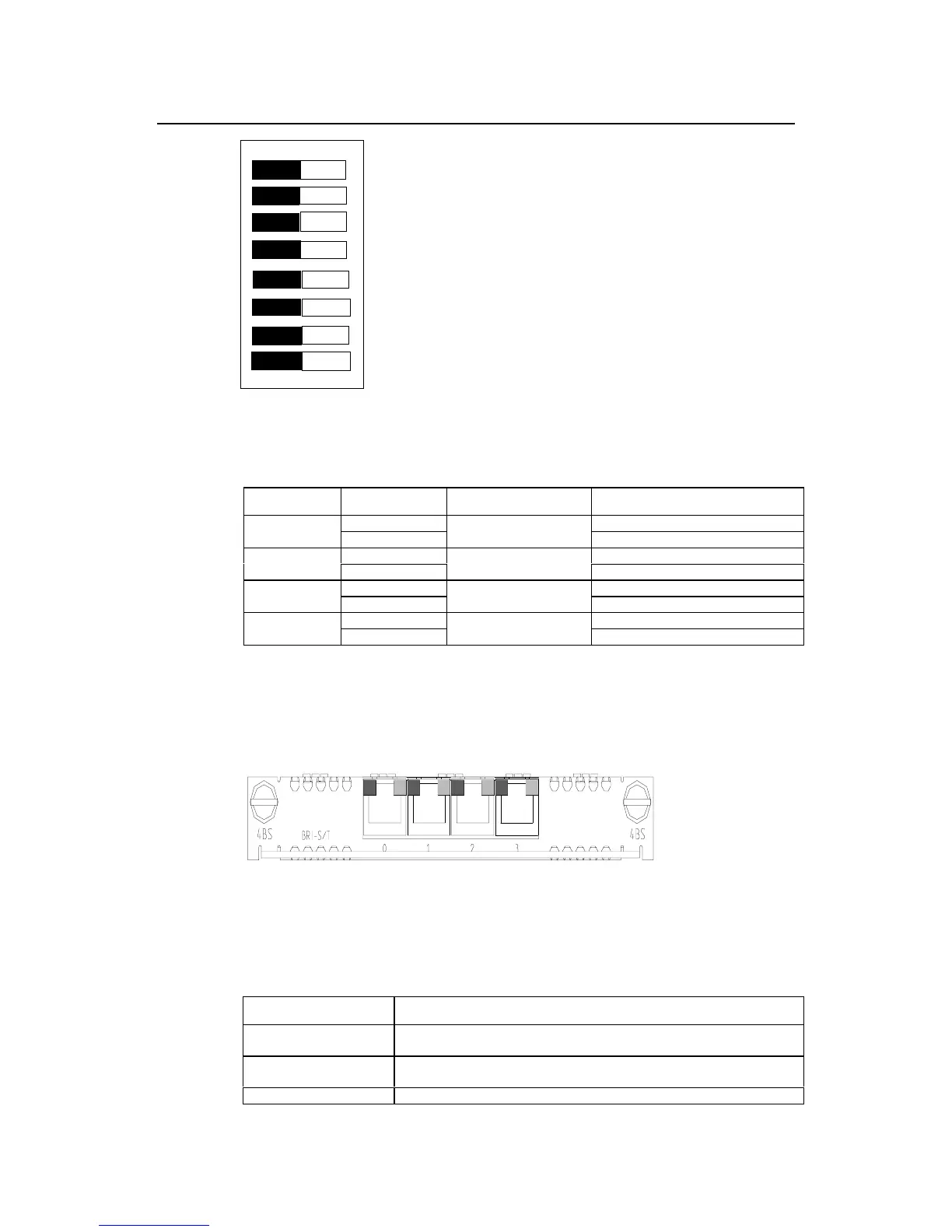
Figure 8-44 DIP switch of 4BS
Table 8-30 Configuration of 4BS DIP switch
Digit Setting method Corresponding channel Description of function
ON 100-ohm matched resistance used
1 and 2
OFF
Channel 0
100-ohm matched resistance not used
ON 100-ohm matched resistance used
3 and 4
OFF
Channel 1
100-ohm matched resistance not used
ON 100-ohm matched resistance used
5 and 6
OFF
Channel 2
100-ohm matched resistance not used
ON 100-ohm matched resistance used
7 and 8
OFF
Channel 3
100-ohm matched resistance not used
8.9.4 Indicators on Panel
The front panel of 4BS is shown as follows:
Figure 8-45 Front panel of 4BS
The meanings of the indicators on 4BS are shown in the following table:
Table 8-31 Meanings of the indicators of 4BS
Indicator Meaning
Yellow lamp on the left
Off means channel B1 is idle. On means channel B1 is occupied and data
communication is going on.
Green lamp on the right
Off means channel B2 is idle. On means channel B2 is occupied and data
communication is going on.
0 - 3 Corresponding port number.
 Loading...


