Installation Manual
Quidway R2600/3600 Series Modular Routers
Chapter 8
Function Modules
8-54
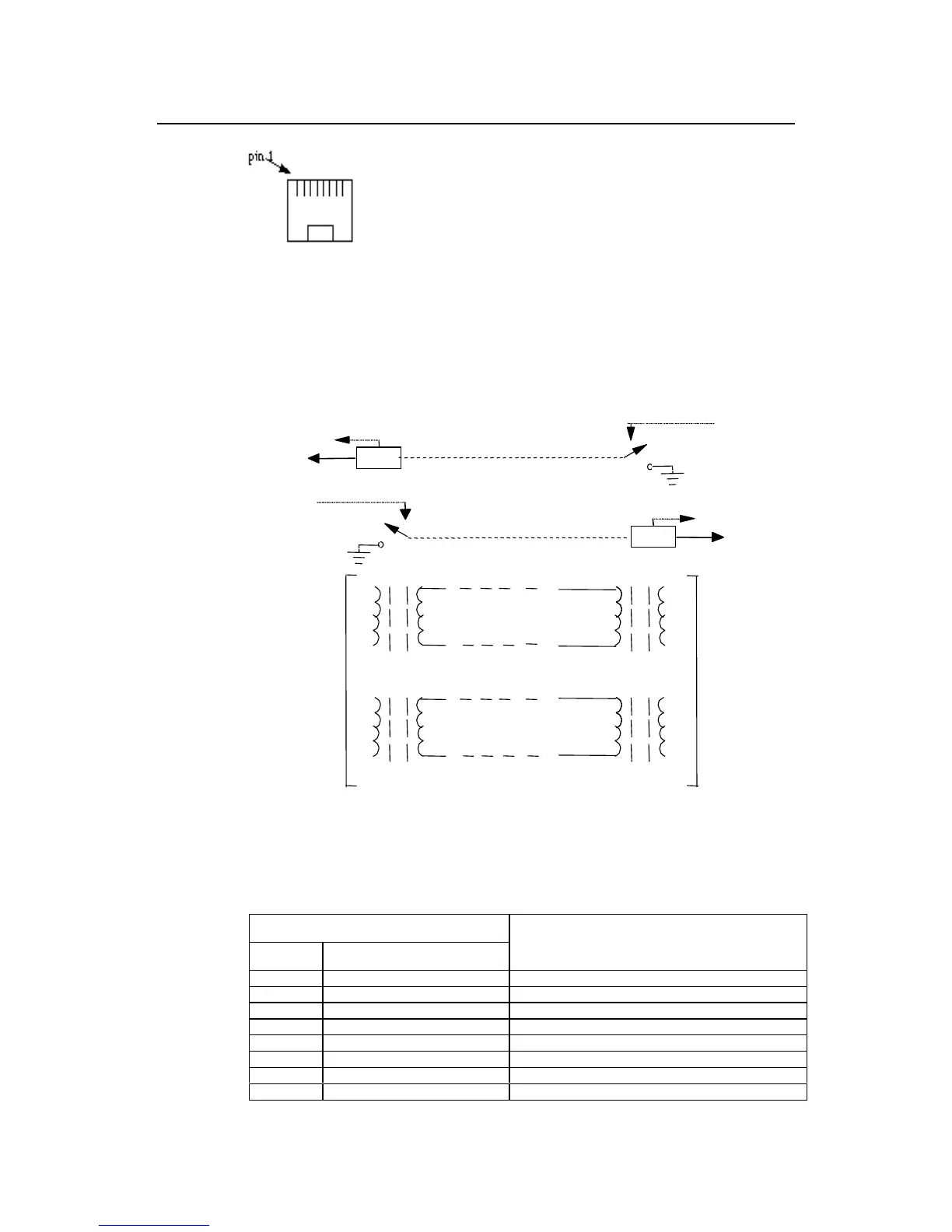
Figure 8-52 Sequence of RJ-45 pinouts
When using Bell V 4-wire mode of connection, the corresponding relationship of RJ-45
pinouts at router side and at the switch side is shown as the following figure.
-48 V
PBX
Router
detect
M
E
7
on-hook
off-hook
on-hook
-48 V
on-hook
detect
M
E
2
off-hook
4- wire
audio
frequency
6
T0
R0
T1
T1
R1
R1
R0
T0
4
5
3
4- wire
audio
frequency
-48 V
Figure 8-53 E&M interface cable assembly (Bell V 4-wire)
Table 8-38 E&M interface cable assembly (Bell V 4-wire)
Router side
RJ-45 Pin RJ-45 interface signal
Switch signal corresponding to Bell V 4-wire
1 SB (negative power supply) ---
2E M
3 RING0 RING0
4 RING1 RING1
5 TIP1 TIP1
6 TIP0 TIP0
7M E
8 SG (negative power supply ground) ---
 Loading...


