Installation Manual
Quidway R2600/3600 Series Modular Routers
Chapter 4
Installation
4-8
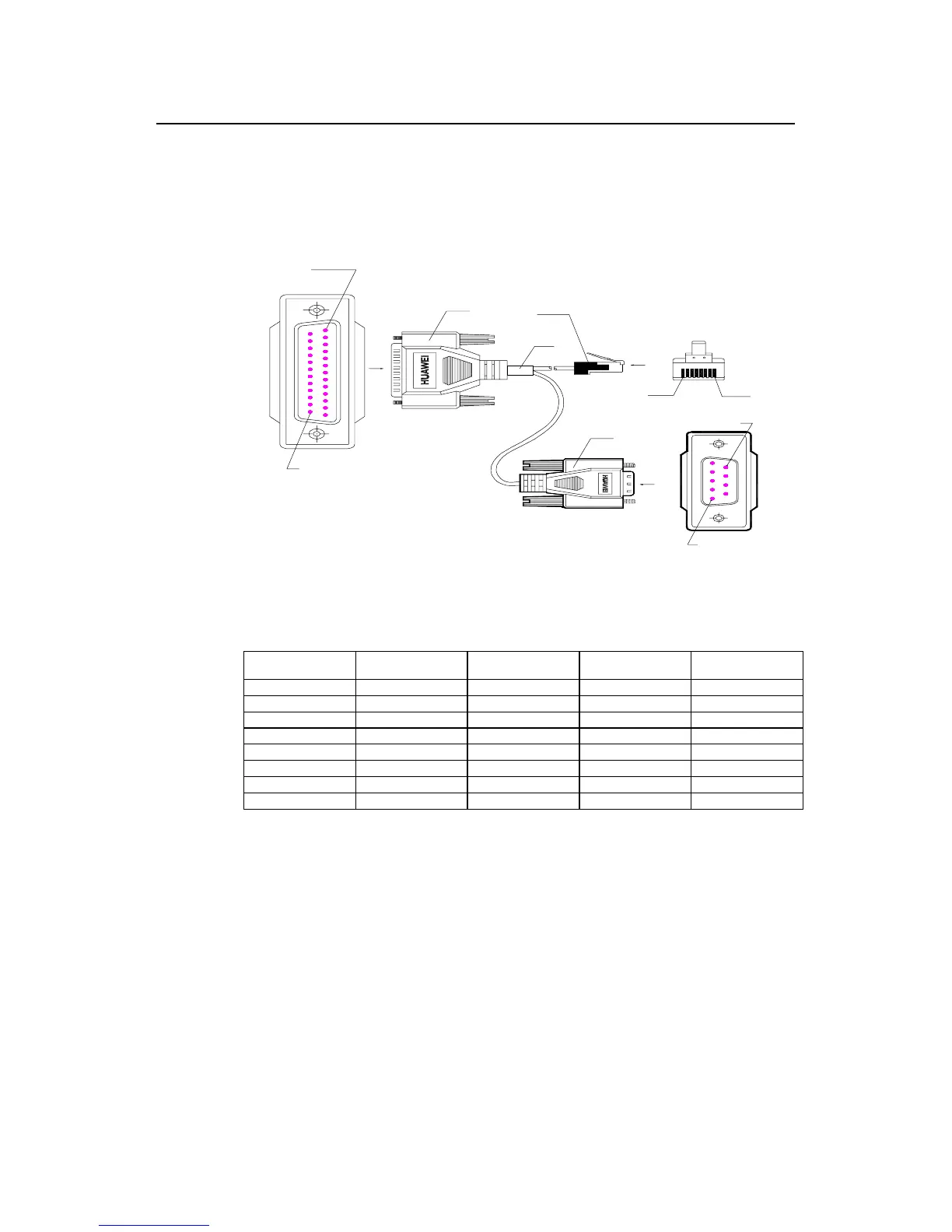
III. AUX cable
The AUX cable is an 8-core shielded cable. One end of it has a RJ-45 connector
adopting RS-232 standard, which is to be connected to AUX. The DB-25-pin and DB-
9-pin connector of the other end are plugged with the DB-25-pin or DB-9-pin socket in
Modem according to the actual requirements. The AUX cable is shown in Figure 4-9:
Enlarged A side
Pos.1
A
Pos. 25
DB25 Male
Label
8P8C PLUG
B
Pos.1 Pos.8
Enlarged B side
DB9 Male
Enlarged C side
Pos.9
Pos.1
C
Figure 4-9 AUX cable
Table 4-4 AUX cable pinouts
RJ-45 Signal Direction DB-25 DB-9
1 RTS ---> 4 7
2 DTR ---> 20 4
3 TXD ---> 2 3
4 DCD <--- 8 1
5 GND --- 7 5
6 RXD <--- 3 2
7 DSR <--- 6 6
8 CTS <--- 5 8
IV. Connecting AUX cable
Complete the connection of AUX cable in reference to Figure 4-10:
Step 1: Plug the RJ-45 end of the AUX cable to the AUX interface of the router.
Step 2: Connect the DB-25 end of the AUX cable to the serial interface of the analog
Modem.
 Loading...


