Installation Manual
Quidway R2600/3600 Series Modular Routers
Chapter 8
Function Modules
8-21
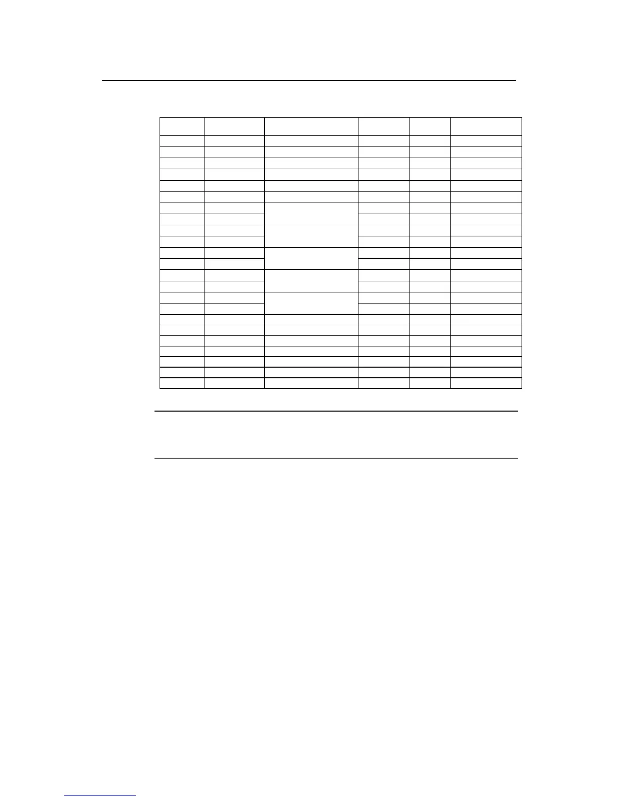
Table 8-15 V.35 DCE cable pinouts (DB-50 ↔34PIN)
DB-50 Signal Description Direction 34 PIN Signal
31 CTS/RTS Twisted pair no. 8
→
CRTS
2 RTS/CTS Twisted pair no. 9
→
DCTS
26 DTR/DSR Twisted pair no. 10
→
EDSR
1 LL/DCD Twisted pair no. 11
→
FRLSD
6 DSR/DTR Twisted pair no. 7
←
HDTR
30 DCD/LL Twisted pair no. 6
←
KLT
20 RxD/TxD+
←
PSD+
44 RxD/TxD-
Twisted pair no. 5
←
SSD-
15 TxD/RxD+
→
R RD+
39 TxD/RxD-
Twisted pair no. 1
→
T RD-
19 RxC/TxCE+
←
USCTE+
43 RxC/TxCE-
Twisted pair no. 4
←
WSCTE-
17 NIL/RxC+
→
V SCR+
41 NIL/RxC-
Twisted pair no. 3
→
X SCR-
16 TxCE/TxC+
→
YSCT+
40 TxCE/TxC-
Twisted pair no. 2
→
AA SCT-
50 GND Single - A Shield_GND
7 GND Twisted pair no. 12 - B Circuit_GND
21 MODE-0 Shorting group GND - -
46 MODE-1 Shorting group GND - -
24 RxD-REST Shorting group GND - -
49 RxC-REST Shorting group GND - -
25 TxC-REST Shorting group GND - -
Note:
The pins not referenced in the above table are not connected.
II.Interaface cable for 4SA module
The 4SA interface is a 100-pin socket.
 Loading...


