7--1
This chapter illustrates the regulations and adjustments of the mechanical
systems (pneumatic systems in the MA version) for correct use of DM 8 G. These
instructions will enable you to ” customise” your machine to suit the type of cuts
you want, optimising the time required to complete them.
Air treatment unit (MA version)
In the MA version of the DM 8, the machine’s pneumatic circuit actuates the vice
by means of a pneumatic cylinder.
The compressed air is treated and purified at the inlet to the system by an air
treatment unit, which, if so calibrated, regulates the pressure at about 6 Bar (87
psi), irrespective of the pressure in use in the factory circuit.
The pressure can in any case be set should the workpiece be subject to deforming
stress or is unstable during the cutting process; the vice should be positioned from
2 to 3 mm from the piece before final clamping.
The user is requested to have available in the workshop a plant having the
characteristics described in CHAPTER 4.
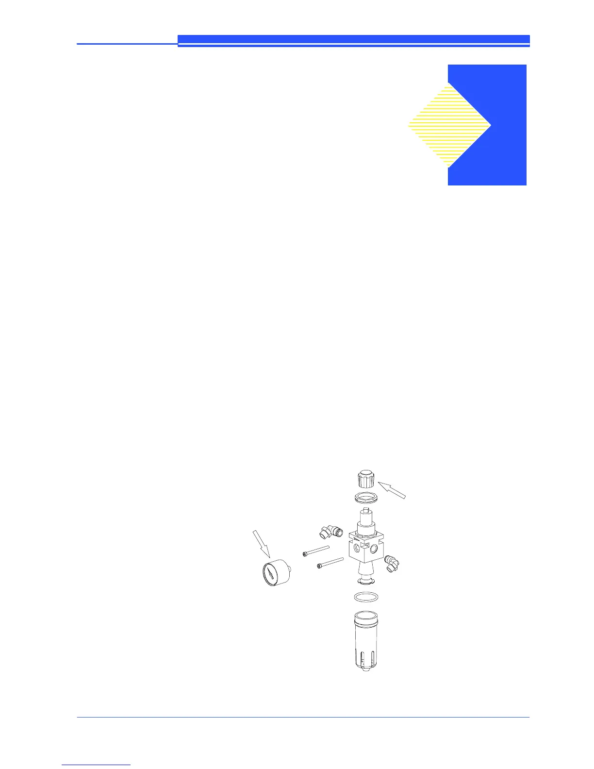
The diagram below shows an exploded view of the air treatment unit: the working
pressure is regulated by rotating the knob indicated by the arrow, and is displayed
on the pressure gauge.
Vice pressure
regulation knob
Pressure
gauge
7
Adjustments