Version 24DM
Diagrams, exploded views and replacement parts 6-- 3
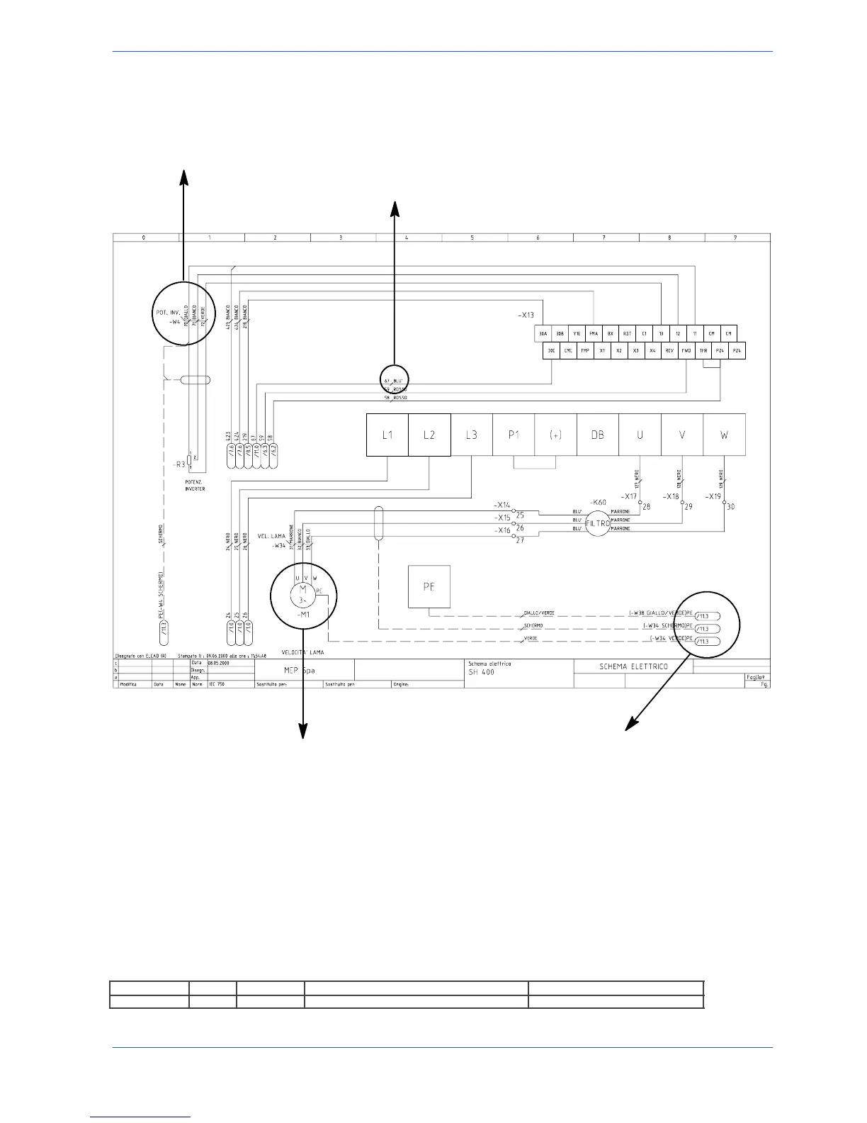
Each component in the wiring diagram is identified by a unique alphanumeric identification code, in com-
pliance with regulations:
The motor is identified by the code --M1
The wire is identified by the
code --W4
These symbols, known as potentials, are used to provi-
de page references: the first number indicates the page
to be referred to, the second number, after the dot, iden-
tifies the column on that page; example /11.8 indicates
that the wire continues on page no. 11 in column 8
This symbol identifies the wire
with its relative number and co-
lour
MARIO ROSSI
The pages following the wiring diagrams contain the following lists:
1. components list (list of all components) and terminals list (list of all the terminals) with the follo-
wing information:
- in--house article code;
- identification code;
- reference, no. of the page and column on which it can be found;
- description;
- manufacturer
ART. COD. ID PRES.REF DESCRIPTION MANUFACTURER
022.2151 -- B 1 /5.2 Strain gauge Deltatec