Chapter 3 Operation
POWER CON
PCON-CB/LC
134
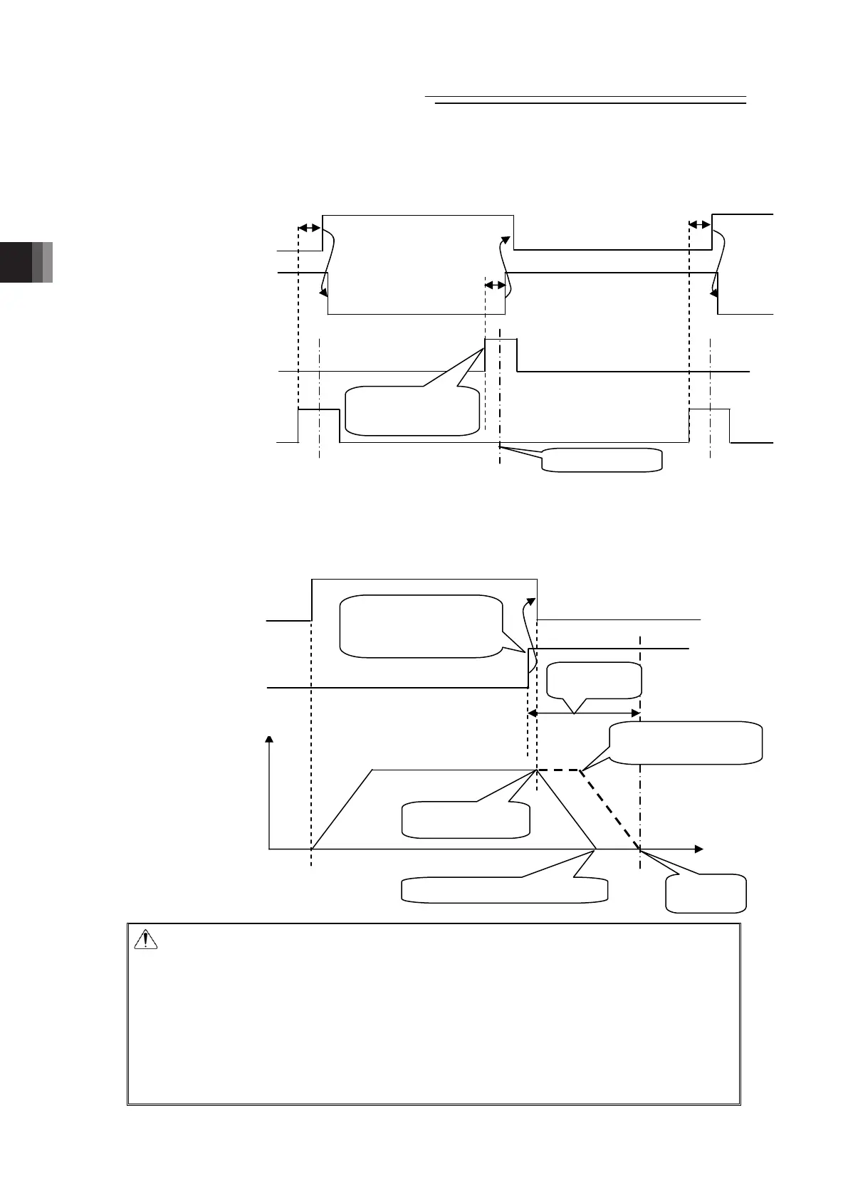
(Example) Repetition of ST1 → ST2 → ST1 →・・・
Insert timer Δt if necessary.
Δt : Time required to certainly reach the target position after the position sensing output LS1 or 2 is turned on.
[Example of stop position when the ST* signal is turned OFF by the LS* signal]
If the positioning width is set at a position before the original deceleration start position, the
actuator cannot reach the target position.
Caution: (1) If the ST* signal for the position is turned ON after the completion of
positioning, the LS* signal remains ON.
(2) Both the LS* and PEND signals are set to ON in the positioning width zone.
Accordingly, they may be turned ON under operation of the actuator if a large
positioning width is set.
(3) Interlock should be taken so that two or more ST* signals are set to ON
simultaneously. If two or more ST* signals are input simultaneously, they will
be executed according to the following priorities: ST0→ST1→ST2
(4) LS* signal would not be output if the positioning width is set less than the
minimum resolution.
Start signal
ST1
(PLC→Controller)
Turned ON after
entering into
positionin
width zone
Target Position
Position sensing output
LS1
(Controller→PLC)
Start signal
ST2
(PLC→Controller)
Position sensing output
LS2
(Controller→PLC)
Δt
Δt Δt
Start signal
ST1
(PLC→Controller)
Turned ON after
entering into
positioning width zone
Target
Position
Position sensing output
LS1
(Controller→PLC)
Operation of actuator
Stop before target position
Orignal deceleration
start position
Positioning
width
Deceleration
start
Velocity
Move
distance

 Loading...


