Chapter 2 Wiring
POWER CON
PCON-CB/LC
65
2.3 Wiring Method
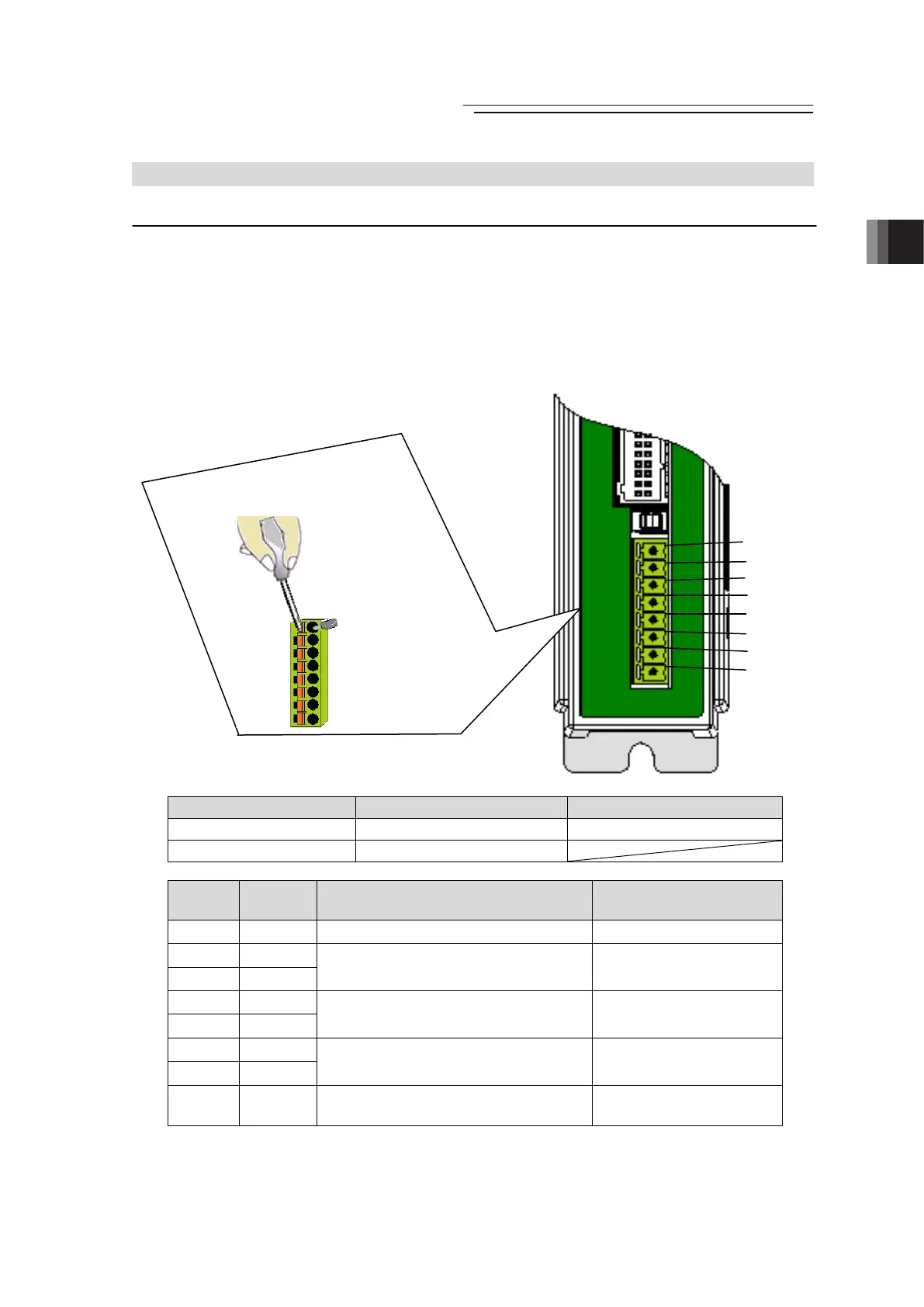
2.3.1 Wiring Layout of Power Supply Connector
The wires of the power supply and the emergency stop circuit are to be connected to the
controller enclosed connector (plug).
Strip the sheath of the applicable wires for 10mm and insert them to the connector.
1) Push a protrusion beside the cable inlet with a small slotted screwdriver to open the inlet.
2) After inserting a cable, remove the slotted screwdriver from the protrusion to fix the cable.
3) After establishing the wiring layout, plug in the enclosed connector to the power connector on
the controller side.
Power Supply Connector Model Remarks
Cable Side FMC1.5/8-ST-3.5 Enclosed in standard package
Controller Side MC1.5/8-G3.5
Pin No.
Signal
Name
Contents Applicable cable diameter
1 EMG- Input of emergency stop status signal
KIV0.5mm
2
(AWG20)
2 0V
3 24V
Power supply input
(24V DC ±10%)
(Note1)
KIV1.25mm
2
(AWG16)
4 MPO
5 MPI
Motor drive power line
KIV1.25mm
2
(AWG16)
6 S2
7 S1
Teaching pendant
Signal of emergency stop push button
KIV0.5mm
2
(AWG20)
8 BK
Brake release power supply input
(Note2)
(24V DC ±10% 150mA)
KIV0.5mm
2
(AWG20)
(Note1) If supplying power with using a 24V DC, having it turned ON/OFF, keep the 0V
connected and have the +24V supplied/cut (cut one side only).
(Note2) The brake is forcibly released when +24V is supplied. Make the 0V in common with
the 0V of the power input.
BK
S1
S2
MPI
MPO
24V
0V
EMG-
3) Plug in the
enclosed
connector to
the power
connector on
the controller
side.
1) Push in a slotted
screwdriver to the
protruded part
2) Insert a wire line

 Loading...


