Chapter 9 Troubleshooting
POWER CON
PCON-CB/LC
214
9.2 Fault Diagnosis
This section describes faults largely divided into four types as follows:
(1) Impossible operation of controller
(2) Positioning and speed of poor precision (incorrect operation)
(3) Generation of noise and/or vibration
(4) Impossible Communication.
9.2.1 Impossible Operation of Controller
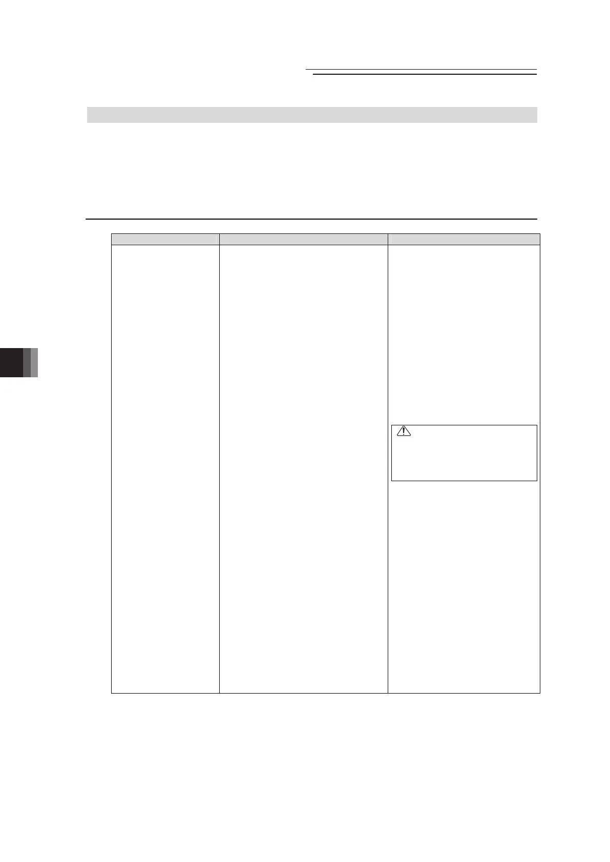
Situation Possible cause Check/Treatment
At power-on, SV on the
status indicator LEDs
does not go ON.
(1) Proper power is not supplied.
(2) Servo-on command (PIO) is not
input to IAI controller.
1) 24V DC power for PIO is not
supplied.
2) Poor contact of flat cable
3) The operation mode setting
switch on the front panel is on
“MANU” side.
(3) Occurrence of alarm.
(4) During emergency-stop.
1) Was the emergency-stop switch.
2) EMG- on the power supply
connector is not connected.
(1) Ensure that appropriate voltage
is supplied and the wiring is in
the right condition.
[Refer to 2.3.1 Wiring Layout of
Power Supply Connector.]
(2) 1) Check the PIO power
voltage. When a large load is
applied to one power source,
there is a risk of power
voltage drop or a shutdown of
the output.
2) Are the PIO cable connectors
inserted to the mating
connectors securely? Check
the input signals on the I/O
monitor of the teaching tool
such as PC software.
Caution
In I/O cable conduction check,
do not widen female pins of the
connectors. Failure to follow this
may cause poor contact.
3) Can such operation as
jogging be performed from
the teaching tool such as PC
software? Set the operation
mode setting switch on the
front panel and restart the
controller.
[Refer to Name for Each
Parts and Their Functions.]
(3) Check the error code with the
teaching tool being connected
and remove the cause by
referring the alarm list.
[Refer to 9.4 Alarm List.]
(4) 1) Release the emergency stop
switch.
2) Check the connection of the
power connector (EMG-).
[Refer to 2.3.1 Wiring Layout
of Power Supply Connector.]

 Loading...


