Chapter 8 Parameter
POWER CON
PCON-CB/LC
178
8.1 Parameter List
The categories in the table below indicate whether parameters should be set or not. There are
five categories as follows:
A : Check the settings before use.
B : Use parameters of this category depending on their uses.
C : Use parameters of this category with the settings at shipments leaving unchanged as a
rule. Normally they may not be set.
D : Parameters of the category are set at shipment in accordance with the specification of the
actuator. Normally they may not be set.
E : Parameters of the category are exclusively used by us for convenience of production.
Changing their settings may not only cause the actuator to operate improperly but also to
be damaged. So, never change the setting of the parameters.
Category do not appear on the teaching tool.
Also, the unused parameter numbers are not mentioned in the list.
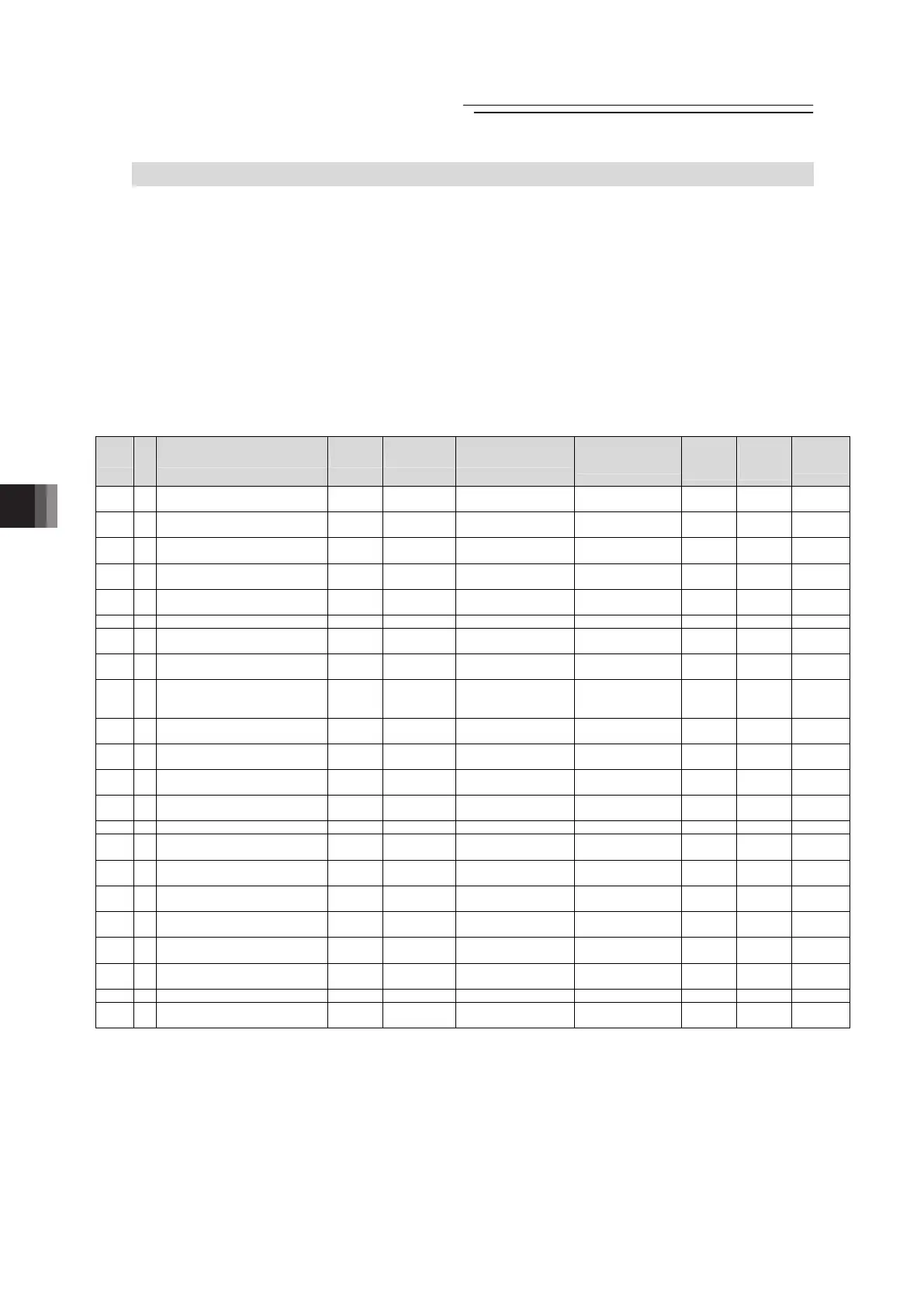
No.
Category
Name Symbol Unit
(Note1)
Input Range
Default factory
setting
for
Positioner
Mode
for Pulse
Train
Mode
Relevant
sections
1 B Zone Boundary 1+ ZNM1
mm
(deg)
-9999.99 to
9999.99
Actual stroke on +
side
(Note2)
{ {
8.2 [1]
8.2 [82]
2 B Zone Boundary 1- ZNL1
mm
(deg)
-9999.99 to
9999.99
Actual stroke on -
side
(Note2)
{ {
8.2 [1]
8.2 [82]
3 A Soft limit+ LIMM
mm
(deg)
-9999.99 to
9999.99
Actual stroke on +
side
(Note2)
{ {
8.2 [2]
4 A Soft limit- LIML
mm
(deg)
-9999.99 to
9999.99
Actual stroke on -
side
(Note2)
{ {
8.2 [2]
5 D Home return direction ORG –
0: Reverse
1: Normal
In accordance with
actuator
(Note2)
{ {
8.2 [3]
6 C Press & hold stop judgment period PSWT msec 0 to 9999 255
{
8.2 [4]
7 C Servo gain number PLGO – 0 to 31
In accordance with
actuator
(Note2)
{ {
8.2 [5]
8.3
8 B Default velocity VCMD
mm/s
(deg/s)
1 to Actuator’s
max. speed
Rated actuator
speed
(Note2)
{
8.2 [6]
9 B Default acceleration/deceleration ACMD G
0.01 to actuator's max.
acceleration/
deceleration
Rated actuator's
acceleration/
deceleration
(Note2)
{
8.2 [7]
10 B Default positioning width INP
mm
(deg)
0.01 to 999.99 0.10
{ {
8.2 [8]
12 B
Current-limiting value at standstill
during positioning
SPOW % 1 to 70 35
{ {
8.2 [9]
13 C
Current-limiting value during home
return
ODPW % 1 to 100
In accordance with
actuator
(Note2)
{ {
8.2 [10]
15 B Pause input disable FPIO –
0: Enabling
1: Disabling
0
{
8.2 [11]
16 B SIO communication speed BRSL bps 9600 to 230400 38400
{
8.2 [12]
17 B
Minimum delay time for slave
transmitter activation
RTIM msec 0 to 255 5
{
8.2 [13]
18 E
Home position check sensor input
polarity
LS – 0 to 2
In accordance with
actuator
(Note2)
{ {
8.2 [14]
21 B Servo ON input disable FPIO –
0: Enabling
1: Disabling
0
{ {
8.2 [15]
22 C Home return offset level OFST
mm
(deg)
0.00 to 9999.99
In accordance with
actuator
(Note2)
{ {
8.2 [16]
23 B Zone Boundary 2+ ZNM2
mm
(deg)
-9999.99 to
9999.99
Actual stroke on +
side
(Note2)
{ {
8.2 [1]
24 B Zone Boundary 2- ZNL2
mm
(deg)
-9999.99 to
9999.99
Actual stroke on -
side
(Note2)
{ {
8.2 [1]
25 A PIO pattern selection IOPN – 0 to 7 0 (Standard Type)
{ {
8.2 [18]
26 B PIO jog velocity IOJV
mm/s
(deg/s)
1 to Actuator’s
max. speed
100
{ {
8.2 [19]
Note 1 The unit (deg) is for rotary actuator and lever type gripper. It is displayed in mm in the teaching tools.
Note 2 The setting values vary in accordance with the specification of the actuator. At shipment, the
parameters are set in accordance with the specification.

 Loading...


