Chapter 2 Wiring
POWER CON
PCON-CB/LC
66
2.3.2 Connection to Actuator
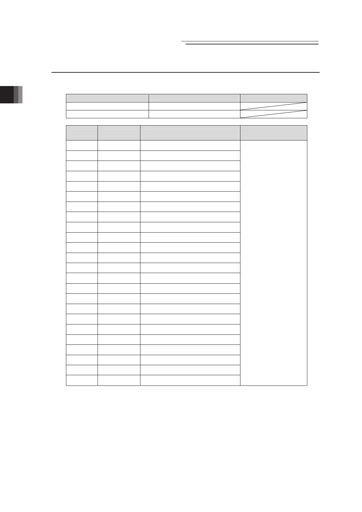
Connect the cables to the motor • encoder connectors.
Motor • Encoder Connector Model Remarks
Cable Side PADP-24V-1-S
Controller Side S24B-PADSS-1
Pin No. Signal Name Contents
Applicable cable
diameter
1
φA
Motor drive phase A
2 VMM Motor power supply
3
φB
Motor drive phase B
4 VMM Motor power supply
5
φ/A
Motor drive/Phase A
6
φ/B
Motor drive/Phase B
7 LS+ Positive side of the limit switch
8 LS- Negative side of the limit switch
9 BK+ Positive side of the brake release
10 BK- Negative side of the brake release
11 NC Not used
12 NC Not used
13 A+ Encoder A-phase differential + input
14 A- Encoder A-phase differential - input
15 B+ Encoder B-phase differential + input
16 B- Encoder B-phase differential - input
17 CA5V CA/CB Encoder power
18 /PS Encoder line driver enable output
19 GND Ground
20 LSGND Ground for limit switch
21 CFB5V Encoder power output for CFB
22 NC Unconnected
23 NC Unconnected
24 FG Grounding
Cable dedicated for IAI
products
* Cable for CB and
cable for CFB are
different.

 Loading...


