Chapter 10 Appendix
POWER CON
PCON-CB/LC
236
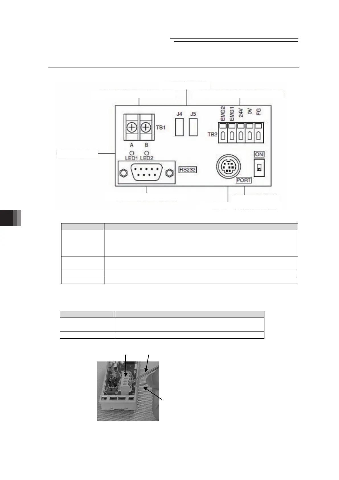
10.1.5 SIO Converter
The SIO converter converts the communication mode from RS232C to RS485 or vice versa.
1) Power/Emergency Stop
Terminal Board (TB2)
2) Link-connection
Terminal Board (TB1)
3) D-sub, 9-pin Connector
6) LED Indicators
for Monitoring
7) e-CON Connector
4) Mini DIN, 8-pin Connector
5) PORT Switch
1) Power/Emergency Stop Terminal Board (TB2)
Symbol Description
EMG1, EMG2 Turn the PORT switch ON to output the emergency stop switch signal, OFF
to short-circuit EMG1 and EMG2.
When applying the emergency stop switch of the teaching pendant to the
emergency stop of the system, obtain the signal from here.
24V Positive side of the 24V DC power supply (Power supply for the teaching
pendant and conversion circuit.)
0V Negative side of the 24V DC power supply
FG Frame ground
(Note) 0V is connected to the pin No. 7 (GND) on the communication connector for the controller.
● Connection method
Use a connection cable satisfying the following specifications :
Item Specification
Applicable wire
Solid Wire : φ0.8 to 1.2mm/Stranded : AWG Size 20 to 18
(0.5 to 0.75mm
2
)
Stripped wire length 10mm
Use for Continuity Check Insert a flathead scewdriver with a bit size of approx. 2.6mm.
Connection Cable

 Loading...


